Defender 90 / 110 / 130. Manual - part 164
DEFENDER
ENGINE
.
I
TIMING BELT
Service Repair
No.
12.65.18
Renew
Disconnect t h e battery.
2. Remove the fan and viscous coupling
assembly,
see operation
3. Slacken and remove the power steering pump
drive belt,
see operation 57.20.14.
4. Slacken and remove the air conditioning
compressor drive belt.
5. Remove the air conditioning compressor from
the mounting bracket but d o not detach the
fluid hoses from the compressor. Move the
compressor aside taking care not t o strain the
Assembling
hoses.
6.
Remove the compressor mounting bracket
7.
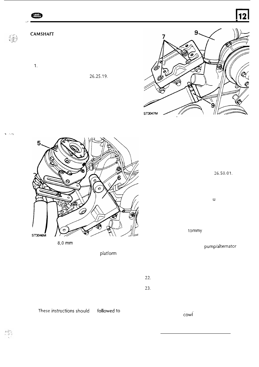
Using an
Allen Key, remove the four
socket headed bolts that secure the
compressor bracket mounting
t o the
front cover and cover plate.
8.
Remove the water pump and alternator drive
belt, s e e operation 86.10.02 insturctions 4 t o
7.
9. Remove the hoses from the water pump.
NOTE: From this stage onwards reference
should be made t o the instructions in the
ENGINE
OVERHAUL
section 12.
SEE INDEX:-
Operations
with
engine installed in vehicle.
b e
the
point when the timing belt has been fitted and
the engine and injector pump are correctly
timed.
10.
Fit the front cover plate using a new gasket
and a new gasket washer o n the centre bolt
boss.
11.
Secure the cover with the various length bolts
tightening evenly t o the correct torque.
Refer
t o the bolt length chart in ENGINE
OVERHAUL
12. Using a new gasket
fit
the water pump,
see
instructions 9 t o 12 operation
13. Connect the hoses
to the water pump.
14. Fit the air conditioning compressor bracket
mounting platform and secure with the
f o u r
socket headed bolts.
15.
Fit the compressor mounting
bracket.
16.
Refer t o ENGINE
OVERHAUL
for the correct
method
of fitting the crank shaft damper.
17. Fit the pulley t o the damper and evenly tighten
the four bolts t o the correct torque.
18. Fit the water pump pulley and secure with the
four bolts. Use a
bar in the hole
provided t o restrain the pulley while tightening
the bolts.
19. Fit and tension the water
drive
belt.
20. Fit and tension the compressor drive belt. SEE
OPERATION 12.13.02
21. Fit and tension the power steering pump drive
bel.
Fit
the fan cowl into position but d o not
secure t o the radiator until the fan
is fitted.
Fit the fan and viscous coupling assembly
to
the water pump spindle. Tighten the left hand
thread t o the
correct torque using a tommy
bar in the hole provided in the fan pulley
to
restrain the coupling.
24. Secure the fan
to the radiator with the
two nuts and fit the top hose.
35