Defender 90 / 110 / 130. Manual - part 145
ELE
C
T
RICAL E
Q
U
I
PMENT
STARTER MOTOR
-
Paris Rhone
-
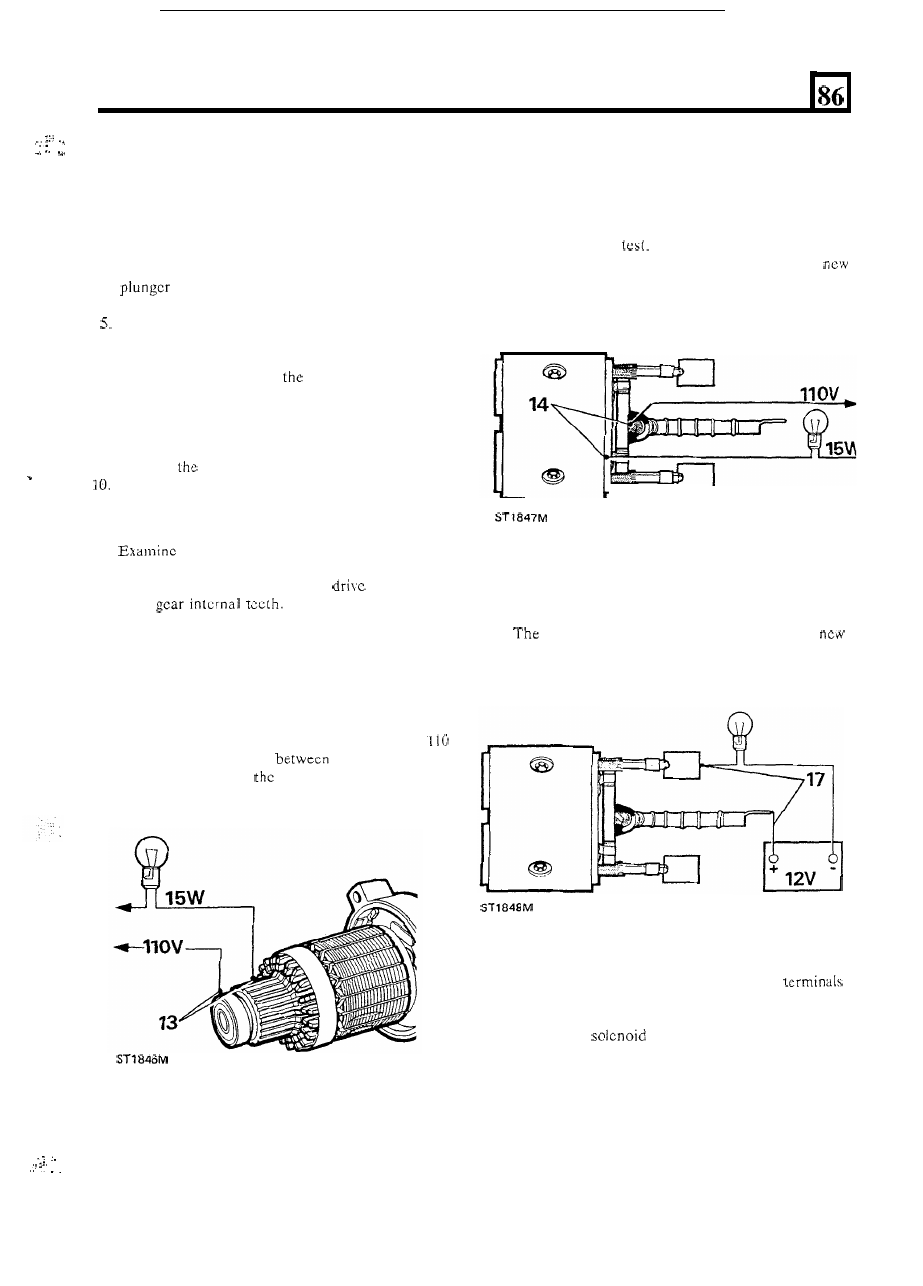
4
cylinder Diesel
Dismantle and Test
,
DISMANTLE
1. Remove starter motor from engine.
2. Disconnect field winding lead from the solenoid.
3. Remove the two nuts and withdraw the solenoid,
and spring.
4. Removc the terminal strap.
Remove the
two through-stud nuts.
6. Remove the brush plate cover.
7.
Withdraw the yoke complete with brush plate
assembly whilst noting
position of the yoke
location plate i n the reduction gear housing.
8. Remove the single socket headed screw and
withdraw the armature and reduction gear housing
from the drive-end bracket.
9. Remove
clutch drive and pinion assembly.
.
Withdraw the brushes from the holders.
Inspection and test
11.
all
parts for condition. Check the
bearings and bushes and pinion drive assembly for
wear. Examine the reduction
pinion and
drive
Check the field coil and
armature brushes.
Armature
12. Using very fine glass paper, clean the commutator
and wipe the surface with a petrol-moistened cloth.
Do not undercut the insulation slots.
13. Check the armature insulation by connecting a
V.A.C. 15
W
test lamp
each commutator
segment in turn and
armaturc shaft.
The lamp
should not light.
.
,
.
.
. .
Field coil insulation
14.
Connect a 110
V.A.C.
15
W test lamp between the
disconnected end of the winding and
a
clean part
of
the
yoke,
15. Ensure that the brushes or leads do not touch the
yoke during the
16.
The lamp should not light;
if it does light, fit a
field coil assembly.
.
Field
coil continuity
17. Connect a 12 V battery-opcrated test lamp
18.
lamp should light;
if i t
does not light, fit a
between each brush in turn and a link lead.
field coil assembly.
Solenoid
19. Disconnect
all cables from the solcnoid
and connectors.
20. Connect a 12
V battcry and a 12 V 60 W test lamp
across the
main terminals. The lamp
should not light; if it does light, fit a new solenoid
complete.
21. Leave the test lamp connected and, using the same
12
V battery supply, energize the solenoid by
connecting a 12 V supply between the small
solenoid operating Lucar terminal blade and a
good earth point on the solenoid body.
continued
41