Defender 90 / 110 / 130. Manual - part 116


  Index      Land Rover     Defender 90 / 110 / 130 - service repair manual


Search            


Content   ..  114  115  116  117   ..


Defender 90 / 110 / 130. Manual - part 116


SUSPENSION 

... 

11.  Remove the inner seal and bearing cone. 
12.  If new bearings are to be fitted drift or press out the 

old cups. 

13.  Degrease  and  examine  the  hub  for  cracks  and 

damage  and  renew 

if 

necessary.  Renew  hub 

if 

wheel studs are faulty. 

Assemble 

14.  If  removed, fit the stub axle to the axle casing with 

new joint washer and secure with the six nuts and 

bolts and tighten to the correct torque. 

15.  Fit  new  inner  and  outer  bearing  cups 

to 

the  hub, 

ensuring that  they  are drifted 

or 

pressed  squarely 

into position. 

16.  Fit the inner bearing cone and pack with one of  the 

recommended hub greases. 

Fitting inner oil seal 

17.  Clean the hub oil  seal  housing and ensure that  the 

seal locating surface is smooth and the chamfer on 
the  leading  edge  is  also  smooth  and  free  from 
burrs. 

18. 

Examine  the  new  seal  and  ensure  that  it  is  clean, 

undamaged  and  that  the  garter  spring  is  properly 
located. Even  a  small  scratch  on the seal  lip could 
impair its efficiency. 

19.  Although  the  new  seal  is  already  pre-greased  by 

the  manufacturer,  apply  one 

of  the  recommended 

hub bearing greases to the outside diameter 

of  the 

seal, before fitting, taking care not  to damage the 
lip. 

20.  Place the seal, lip side leading, squarely on the hub 

and  using  the 

76 

end 

of 

seal  replacer  tool 

LST 550-5 

and drift 

550 or 

18 G 

134 drive the seal 

into position  to the depth determined by the tool. 

Fitting outer oil seal 

21.  Fit  the  new  outer bearing cone and pack  with  one 

of the recommended hub greases. 

22.  Carry  out  instructions 

17 

to 

19 but  insert  the  seal 

with the lip side trailing. 

23.  Place the seal, lip side leading, squarely on the hub 

and  using  the 

72 

end 

of  seal  replacer  tool 

LST 

and drift 

or 18 G  134, drive the seal 

into position 

to the depth determined by the tool. 

Fitting hub to stub axle 

24.  Smear  the  lips 

of  both  seals  with  one 

of  the 

recommended  greases. 

This  is  important  since  a 

dry  seal  can  be  destroyed  during  the  first  few 
revolutions 

of 

the hub. 

25. 

Select  a  new  seal  track  spacer  and  check  that  the 
outer diameter  is  smooth and  free from blemishes 

26. 

Taking care not to damage the seal lips fit the hub 
assembly to the stub axle. 

Do 

not allow the weight 

of  the  hub 

to rest,  even  temporarily, 

on 

the  outer 

seal otherwise  damage  and  distortion  could  occur. 
Therefore  hold  the h u t  clear 

of the stub 

until 

the seal track spacer is fitted. 

27.  Carefully fit the seal track spacer, seal lip leading. 

28. 

Fit  the  hub  inner  nut  and  using  spanner  606435 
tighten the adjusting nut whilst slowly revolving 

the 

hub until all end-float is removed then back-off 
nut approximately half-a-turn. 

29.  Mount a dial test indicator and bracket 

on 

the hub 

so that the stylus rests in  a loaded condition on the 
nut.  Check  the  end-float  which  must  be 

0,013  to 

0,010 

(0.0005 

to 

0.0004 in). Adjust  the nut  as 

necessary to achieve this. 

30,  Fit  the locker  and  locknut  and  tighten  against  the 

adjusting nut. 

Rotate the hub several times to settle the bearings 

then re-check the end-float. 

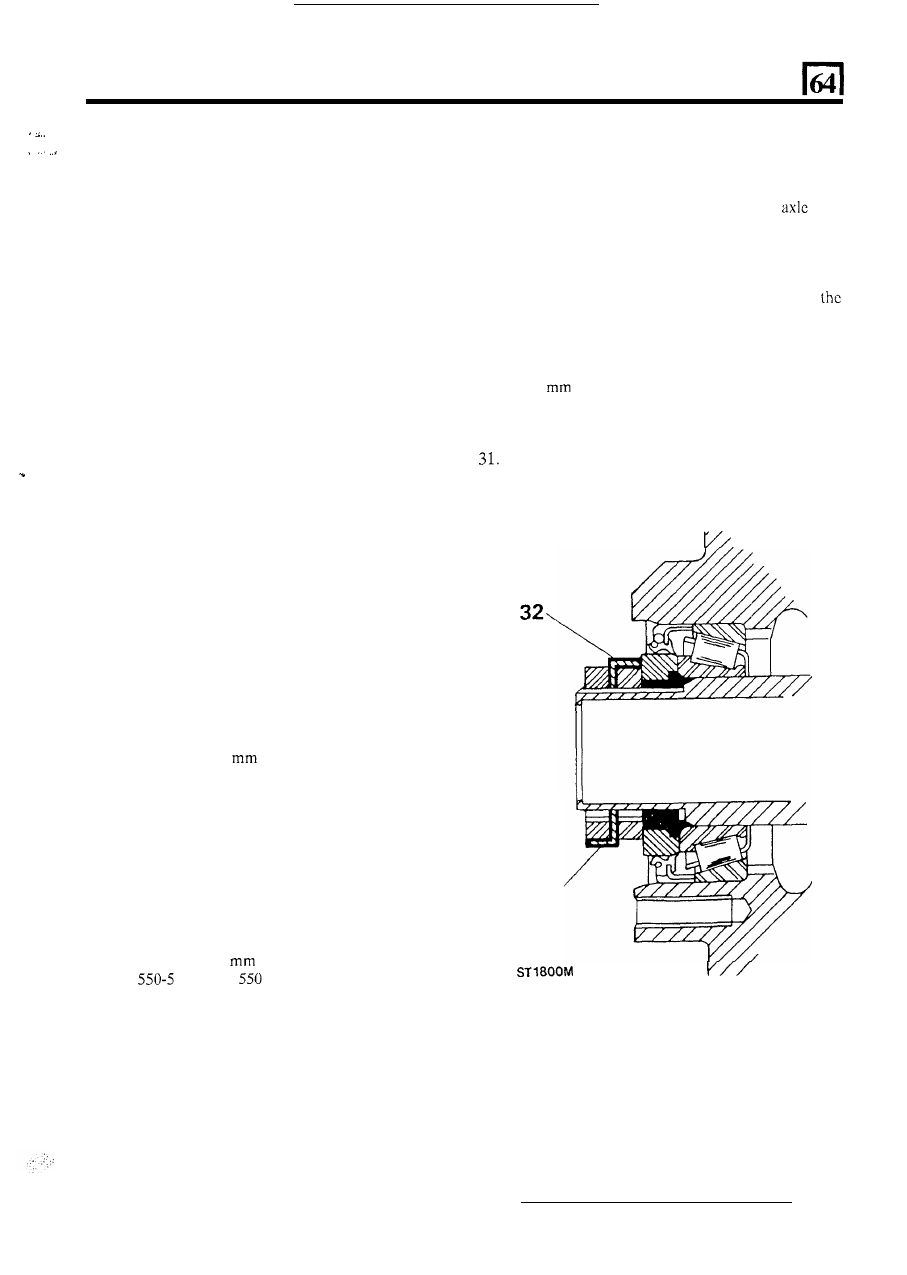
32.  Bend one segment 

of  the locker over the adjusting nut 

and another, diametrically opposite, over the locknut. 

32’ 

33.  Using  a  new  joint  washer,  fit  the  hub  driving 

member  and secure with  the five bolts  and tighten 
evenly to the correct torque. 

34.  Fit  the  circlip  to  the  axle  shaft  ensuring  that  it  is 

properly seated in the groove. 

35.  Fit the 

hub 

cap. 

36.  Fit  the  road  wheels  and  secure  with  the  nuts. 

Jack-up  the vehicle,  remove  axle stands and lower 
vehicle  to  ground.  Finally  tighten  the  road  wheel 
nuts to the correct torque. 

and  that  there  are  no  burrs 

on  the  chamfered 

leading edge. 

11 

SU

S

PENSI

ON 

ST 

KEY 

TO HUB COMPONENTS 

1.  Hub cap. 

2.  Circlip. 
3.  Spring washer-  

hub driving member bolt. 

4. 

Hub driving member. 

5. 

Hub driving member bolts. 

6. 

Brake drum retaining screws. 

8. 

Outer bearing cup. 

9.  Inner bearing cup. 

10.  Inner bearing cone. 
11.  End-float adjustingnut. 
12.  Inner oil seal. 
13.  Joint washer. 

7. 

bearing 

stub axle to axle casing 

14.  Locknut. 
15.  Bolt. 
16.  Axle shaft 

17. 

Locknut. 

18. 

Lock washer. 

19. 

Joint washer. 

21.  Hub casting. 
22.  Brake drum. 
23.  Outer oil seal. 
24.  Road wheel 

stud. 

25.  Stub axle. 

12 

S

U

S

PEN

SION 

OVERHAUL REAR SUSPENSION 

Remove the lower links 

1.  Jack up the rear of  the vehicle and lower on to axle 

stands. 

2.  Remove 

the nut and bolt retaining the lower link to 

the axle bracket. 

3.  Remove  the  three  nuts  and  bolts  retaining  the 

foward end of the link to the chassis bracket. 

4.  Withdraw the lower link from the vehicle. 
5.  Remove  the  locknut  and  washer  and  remove  the 

flexible mounting from the link. 

Renew the bushes 

6.  Press out the bush  from  the rear  end of  the  lower 

link. 

7.  Press in a new bush squarely into the link. 

Fit the lower link 

8. 

Assemble  the  flexible  mounting  to  the  link  and 

secure with  the  locknut  but  do not  tighten  at this 
stage. 

9. 

Fit the link to t h e  vehicle, securing the front end of 

the 

link  to  the chassis  bracket  with  the three  nuts 

and bolts. 

10.  Assemble  the  rear  end  of 

the  link  to  the  axle 

bracket and retain with the nut and bolt, but d o  not 
tighten at this stage. 

11. 

Lower  the  vehicle  to  the  ground  and  allow  the 

suspension to settle. 

12.  Tighten the nut and bolt at the rear end of the link. 
13.  Tighten 

the 

forward 

locknut 

to 

176 

(130  lbf  ft). 

Remove upper links 

22.  Using ball joint extractor 

tool 

or a suitable 

proprietry  tool remove  the ball joint  from  the axle 
bracket. 

23.  Remove the  pivot  bracket  complete with  the  ball 

joint  and 

if 

fitted,  the  lower  ball  joint 

of 

the 

levelling unit. 

24.  Remove the two bolts securing the ball joint to the 

pivot  bracket  and  press  the  ball  joint  from  the 
bracket. 

NOTE:  Replacement  ball  joints  are  supplied  as 
complete assemblies packed with grease. 

25.  Using  two  bolts  as  a  guide  to  ensure  correct 

alignment press the knurled ball joint into the pivot 
bracket and secure with the two 

nuts and bolts. 

Assemble upper links and ball joints 

26.  Fit  the pivot  bracket  ball  joint  and  bracket  to  the 

axle and secure with the plain washer 

nut and 

split pin. Tighten the nut to 176 

(130 Ibf  ft). 

27. 

Fit the levelling unit, if used. 

28.  Assemble the upper links to the chassis attachment 

brackets  but  do not  at  this  stage  fully  tighten  the 
pivot nut and bolt. 

29.  Fit the upper link 

to 

the chassis with 

t h e  

six  nuts  and  bolts,  (three  each  side).  Note  the 
positions 

of  the  bolt  heads.  Tighten  the  nuts  to 

47 

(35 lbf  ft). 

30.  Secure the rear ends of  the upper links to the pivot 

bracket  and  tighten  the  two  nuts  and  bolts  and 
tighten to 115 

(85 Ibf  ft). 

31.  Remove  the  jack  from  the  chassis,  allow 

suspension  to  settle  and  tighten  upper  link  pivot 
bolts. 

14. 

16. 

17. 

18. 

19. 

Jack  up  the  vehicle  under  the  chassis 

so  that  the 

rear axle 

is freely suspended. 

bracket 

to the chassis frame. 

Remove the two nuts and bolts securing the upper 

links to the pivot bracket. 
Withdraw the upper links complete with the chassis 
attachment brackets from vehicle. 
Remove the nut and bolt  retaining  forward end of 

the link to the chassis bracket  and separate the two 
parts. 

Press 

out  the  bush  from  the  forward  end 

of  the 

Renew anti-roll bar bushes and ball joints 

32.  Remove  the  two nuts  and  bolts  securing the 

roll bar to the axle link. 

33. 

Remove  the  eight  nuts  and  bolts  (four each  side) 

retaining the anti-roll  bar to the chassis and remove 
the bar from the vehicle. 

34.  Remove the split pin and castle nut and remove the 

ball joint and link from the axle location. 
If  the ball joint requires replacement the complete 
link must be renewed. 

35.  Renew  the  rubbers  and  fit  the  anti-roll  bar  to  the 

chassis  and  secure  with  the  eight  bolts  and  nuts 
tightening to 24 

(18 lbf  ft). 

36.  Fit  the ball  joint  and link to the  axle  location  and 

links 

press 

bushes. 

Renew pivot bracket ball joint 

tighten  the castle nut  to  176 

(130 lbf  ft) and fit 

a new split pin. 

-

-


20.  Remove the levelling unit -if fitted. 
21.  Remove the  split  pin,  castle  nut  and  plain  washer 

37.  Fit the anti-roll bar to the ball joint link and fit new 

bushes  in  the  sequence illustrated  and  tighten  the 
nuts and bolts, to the correct torque. 

13 

securing the ball joint to the pivot  bracket. 

12 

1.  Salisbury axle casing 

2.  Anti-roll  bar 

3. 

Boge self levelling unit 

4. 

Levelling unit upper ball joint assembly 

5.  Levelling unit lower ball joint assembly 

6. 

Fulcrum bracket 

7.  Fulcrum bracket ball joint assembly 
8.  Suspension top links 
9.  Top link 

brackets 

10. 

Top link bushes 

11.  Lower links 

REAR SUSPENSION 

12.  Lower 

link flexible bush assembly 

13. 

Lower link bush and bolt assembly 

14.  Coil spring assembly 
15. 
16.  Shock absorber 
17.  Shock absorber top bush assembly 
18.  Shock absorber lower bush assembly 
19.  Anti-roll bar bush and strap assembly 

20.  Anti-roll bar ball joint and link assembly 
21.  Heavy duty Rover axle casing 


Content   ..  114  115  116  117   ..