Defender 90 / 110 / 130. Manual - part 107


  Index      Land Rover     Defender 90 / 110 / 130 - service repair manual


Search            


Content   ..  105  106  107  108   ..


Defender 90 / 110 / 130. Manual - part 107


STEERING 

6. 

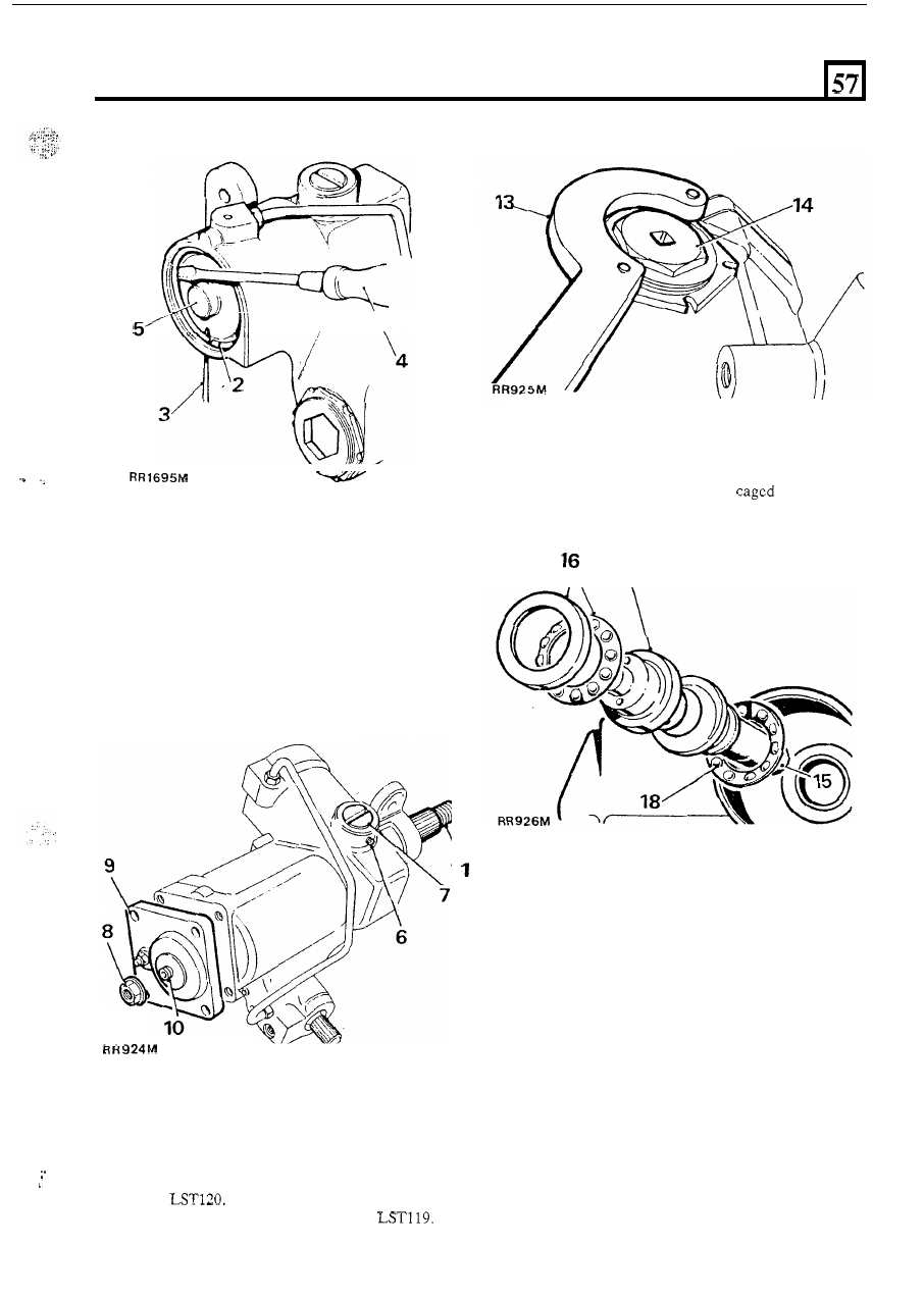
Slacken  the  grub  screw  retaining  the  rack  pad 

7. 

Remove the rack pad adjuster. 

8. 

Remove the sector shaft adjuster locknut. 

9.  Remove the sector shaft cover fixings. 

adjuster. 

10.  Screw in  the sector shaft adjuster until  the cover is 

11.  Slide out the sector shaft. 

removed. 

15. 

Tap the splined end of the spindle shaft  to free the 

16.  Withdraw  the  bearing  cup and 

ball  bearing 

bearing. 

assembly. 

17 

17.  Withdraw the valve and worm assembly. 
18.  Withdraw  the  inner  bearing  ball  race  and  shims. 

Retain the shims. 

continued 

12.  Withdraw the piston, using a suitable bolt screwed 

13.  Remove  the  worm  adjuster  locknut  using 

‘C’ 

14. 

Remove the worm adjuster 

using socket 

into the tapped hole in the piston. 

spanner, 

21 

S

TEERING 

Steering box seals 

19.  Remove the circlip  and seals from the sector shaft 

Steering box casing 

22.  If  necessary,  replace  the  sector shaft  bush,  using 

23.  Examine  the  piston  bore  for traces 

of  scoring  and 

housing bore. 

NOTE:  Do  not  remove  the  sector  bush  unless 

wear. 

replacement is required.  Refer to instruction 22. 

suitable tubing as a drift. 

Remove  t h e  circlip  and  seals from  the  input  shaft 

housing bore. 

22 

23 

24.  Examine  the  inlet  tube  seat  for  damage.  If 

replacement is necessary this can be undertaken by 
using a suitable tap. 

25.  Examine the feed tube for signs of  cracking. 

NOTE: 

Do  not  remove  the  input  shaft  needle 

bearing unless replacement 

is 

required. 

26.  Check that there is no side play on the rollers. 
27.  If  excessive side play on the roller does exist renew 

28. 

Check the condition 

of  the adjuster screw threads. 

29.  Examine  the  bearing  areas  on  the  shaft  for 

uneven 

or  excessive 

Inspecting 

21.  Discard all rubber seals and provide replacements. 

the sector shaft. 

excessive wear. 

wear. 

NOTE:  A  rubber  seal  is  fitted  behind  the  plastic 
ring  on  the  rack 
plastic ring and provide replacements. 

22 

STEERING 

Sector shaft cover assembly 

... 

31. 

The 

cover,  bush  and  seat  are  supplied  as  a 

complete assembly 

for replacement purposes. 

Sector shaft adjuster locknut 

32. 

The locknut  functions also as a fluid seal and must 
be replaced  at overhaul. 

Valve and worm assembly 

33.  Examine  the  valve  rings  which  must  be free from 

cuts, scratches and grooves. The valve rings should 
be a loose fit in the valve grooves. 

I

.


34.  Remove  the  damaged  rings  ensuring  that  no 

damage is done to the seal grooves. 

35. 

If 

required,  fit  replacement  rings,  using  the  ring 

expander 

Both  rings  and  tool  may  be 

warmed  if  found necessary.  Use hot water for this 
purpose.  Then  insert  into  the  ring  compressor 
606603 to cool. 

NOTE:  The  expander  will  not  pass  over  rings 
already  fitted.  These  rings  must  be  discarded  to 
allow access then renewed. 

36.  Examine  the  bearing  areas  for  wear.  The  areas 

must be smooth and not indented. 

37.  Examine  the  worm  track  which  must  be  smooth 

and not indented. 

38. 

Check 

for 

wear  on  the  torsion  bar  assembly  pins; 

no  free movement  should 

between  the  input 

shaft and the worm. 

NOTE:  Any sign of  wear makes it essential that the 
complete valve and worm assembly 

is 

renewed. 

bearing and cage assemblies 

39.  Examine  the  ball  races  and  cups  for  wear  and 

40.  If  the ball cage has worn against the bearing cup, 

fit 

general condition. 

replacements. 

41.  Bearing balls must be 

by the cage. 

42.  Bearings  and  cage  repair  are  carried  out  by  the 

complete  replacement 

of  the  bearings  and  cage 

assembly. 

43.  To  remove  the  inner  bearing  cup  and  shim 

washers, jar the steering box on  the work bench, 

or 

use a suitable extractor. 

NOTE:  Should 

be  experienced  at  this 

stage,  warm  the  casing  and  the  bearing  assembly. 
Cool  the  bearing cup using a  suitable mandrel and 

j a r  the steering box on the bench. 

continued 

23 

S

TEERING 

Rack thrust pad and adjuster 

44.  Examine the thrust pad for scores. 
45.  Examine the adjuster for wear in the pad seat. 
46.  Examine 

nylon  pad for distortion and  adjuster 

grub screw assembly for wear. 

46 

45 

44 

Rack and piston 

47.  Examine for excessive wear 

on 

the rack teeth. 

48.  Ensure  the  thrust  pad  bearing  surface  is  free  of 

scores and wear. 

Input shaft needle bearing 

52.  If 

necessary,  replace the bearing. The replacement 

must be fitted squarely in  the bore (numbered face 
of  the  bearing  uppermost).  Then,  carefully  push 

the  bearing  in  until  it  is  flush  with  the  top  of  the 
housing bore. Ideally, the bearing will  be just clear 

of 

the bottom 

of 

the housing bore. 

Reassemble 

NOTE:  When  fitting  replacement  oil  seals,  these  must 
be lubricated with recommended fluid. 

Also 

ensure that 

absolute cleanliness 

is observed during assembly. 

Input shaft oil seal 

53.  Fit  the  seal,  lipped  side  first,  into  the  housing. 

When correctly seated, the seal backing will lie flat 

on 

the bore shoulder. 

Fit the extrusion washer and secure with the circlip. 

49.  Ensure  that  the  piston  outer  diameters  are  free 

from burrs and damage. 

50.  Examine  the  seal  and  ring  groove  for  scores  and 

damage. 

51.  Fit a new rubber ring to the piston. Warm the white 

nylon seal and fit this to the piston. Slide the piston 
assembly 

i n t o  

the  cylinder  with  the  rack  tube 

outwards. Allow to cool. 

24 


Content   ..  105  106  107  108   ..