Defender 90 / 110 / 130. Manual - part 104
STEERING
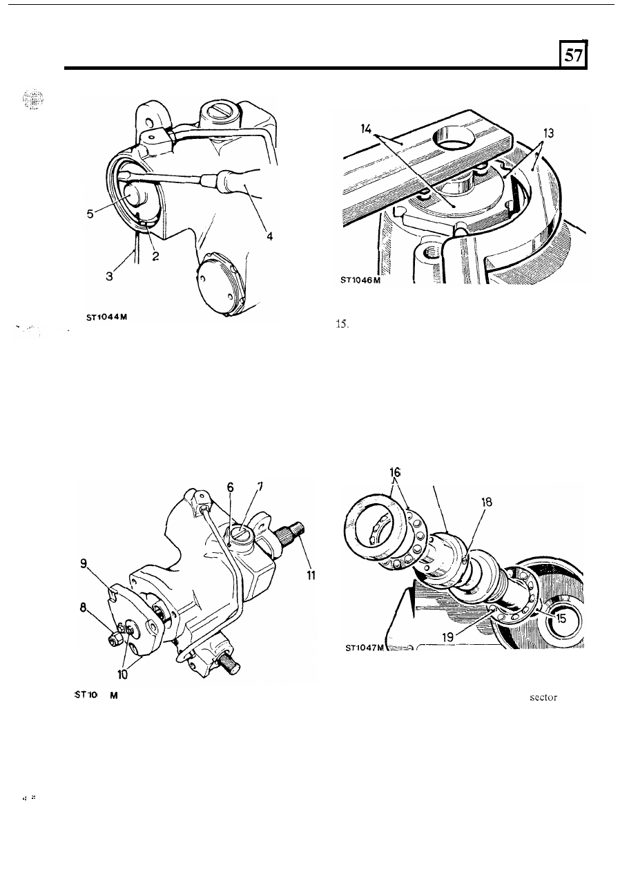
Tap the splined end
of the spindle shaft to free the
bearing.
16. Withdraw the bearing cup and caged ball bearing
17. Withdraw the valve and worm assembly.
18. Do not disturb the trim screw, otherwise the
calibration will be adversely affected.
19. Withdraw the inner bearing ball race and shims.
Retain the shims.
6. Slacken the grub screw retaining the rack pad
7.
Remove the rack pad adjuster.
8.
Remove the sector shaft adjuster locknut.
9.
Remove the sector shaft cover fixings.
assembly.
adjuster.
10. Screw in the sector shaft adjuster until the cover is
removed.
11. Slide out the sector shaft.
4
5
17
Steering
box
seals
20. Remove the circlip and seals from the
shaft
housing bore.
NOTE: Do not remove the sector bush unless
replacement
is required. Refer to instruction 23.
21. Remove the circlip and seals from the input shaft
housing bore.
NOTE: Do not remove the input shaft needle
bearing unless replacement is required.
12. Withdraw the piston, using a suitable
UNC
bolt
13.
Remove the worm adjusting screw locknut using
14.
Remove the worm adjusting screw using peg
screwed into
the tapped hole in the piston.
‘C’
spanner
606600.
spanner
606601.
continued
9