Defender 90 / 110 / 130. Manual - part 87
FI
VE S
P
E
ED GEARBOX
.:i
.
,
...
..
...
,
gear to bush end float
5th gear end float
7. Fit 5th gear thrust washer, 5th gear, needle bearing
and spacer followed by synchromesh unit but
leaving out the baulk ring at this stage. Press down
on the synchro inner member and
the gear
end
float
as shown;
this tolerance, again is identical
to 3rd gear.
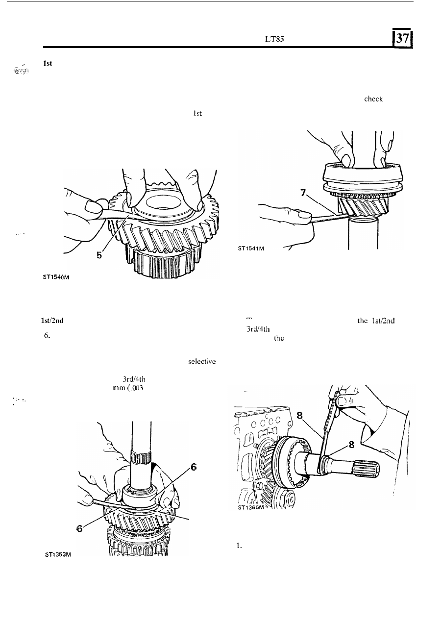
5.
To carry out 1st gear check, it is not necessary
to
assemble the components on
to the mainshaft.
Assemble 1st gear
on
to
the bush and using a
suitable straight edge
or flat plate (the oil pump
back plate is ideal) check the end float
of
gear
on the bush as shown. The tolerance is identical
to
.
.
I
.
3rd and 2nd gear end floats.
synchromesh
end
float
Next fit
the 1st gear baulk ring, 1st gear bush and
gear, original selective washer, dummy bearing
LST 101 and circlip onto the shaft, then check the
end float as shown. Choose a suitable
shim washer to obtain the correct tolerance which
is identical with
synchromesh, i.e.
minimum
to
0,075
in).
.
.
-6
5th
gear
synchro end float
8.
Fit the 5th gear synchromesh backing plate, seal
collar, original selective shim washer and circlip.
Then check the clearance as shown; select
a
suitable shim washer t o minimise the clearance.
I
his adjustment is identical
to
and
synchromesh units.
With all
mainshaft adjustments correct, remove
the 5th gear componcnts ready for assembly.
5th gear selector fork and bracket assembly
Remove slipper pads from selector fork and check
2.
If necessary, remove circlips and remove selector
3.
Clean all componcnts and refit in reverse order.
for wear.
fork pivot pins.
77