Defender 90 / 110 / 130. Manual - part 85


  Index      Land Rover     Defender 90 / 110 / 130 - service repair manual


Search            


Content   ..  83  84  85  86   ..


Defender 90 / 110 / 130. Manual - part 85


LT85 

FIVE SPEED GEARBOX 

..: 

27.  T a p  down 

jaw  roll  pin  until  jaw  is 

on 

selector rail. 

.:: 

28.  Withdraw 

selector rail and jaw. 

Remove interlock  from 

sclcctor rail. 

30.  T a p  down 

jaw  roll  pin  until 

is  free  on 

sclector rail. 

31.  Remove clamp bolt  from 

selector  fork  and 

withdraw 

selector rail and j a w .  

32.  Remove interlock  from 

sclcctor 

rail. 

33.  Lift rcverse cross-over 

gearbox. 

34. 

Remove 

and 

selector forks. 

35.  Remove  interlock  plungers  and  also dctcnt 

balls 

if 

not 

removed 

in 

operation 

19. 

Remove 

two 

bolts,  spring  washers  and  plain 

washers  securing  5th  gear  fork  and  bracket 
assembly  to gearbox. 

Do not 

selector fork 

slipper pads when removing fork. 

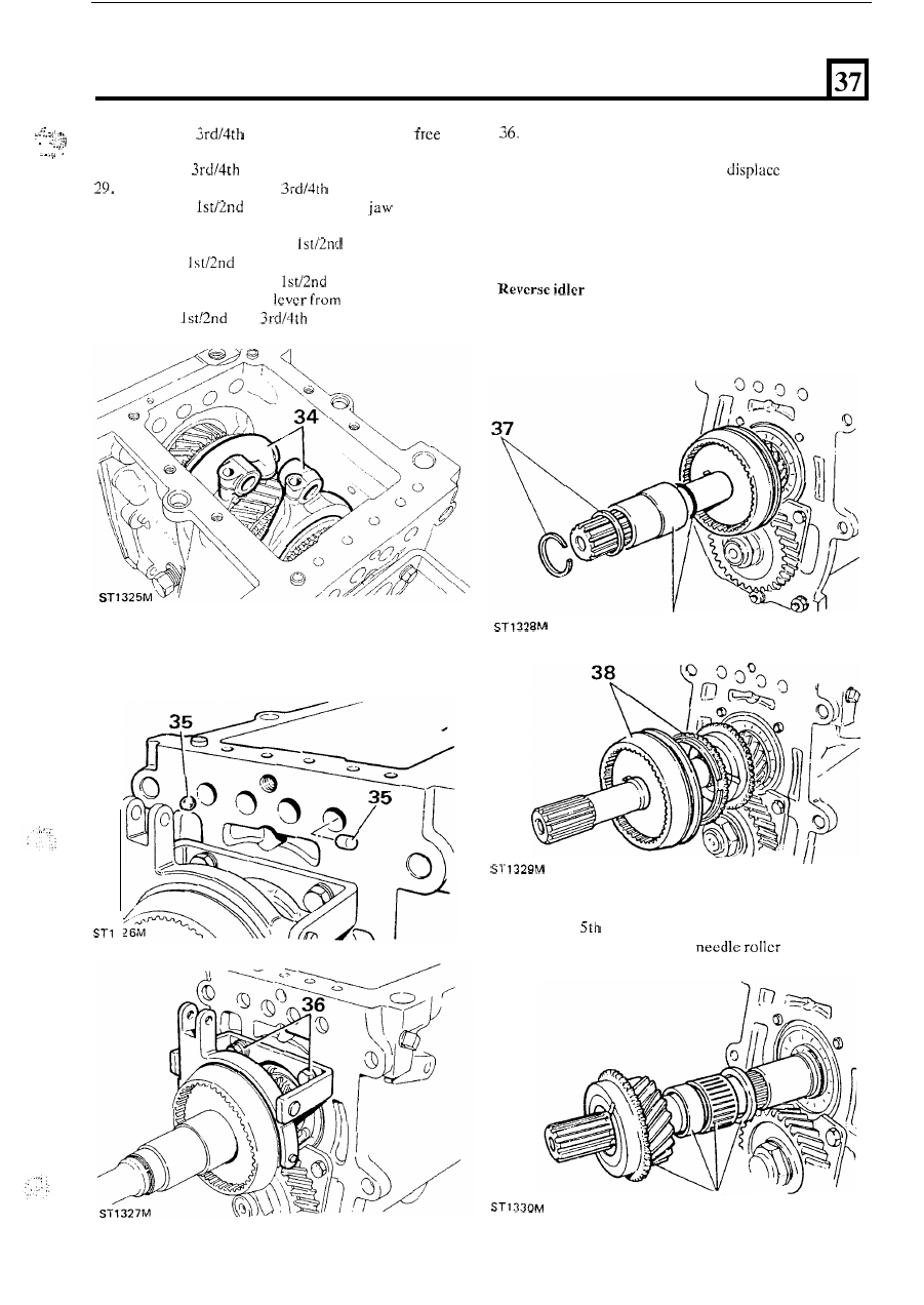
shaft, mainshaft and layshaft 

37.  Remove circlip, selective washer, oil seal collar and 

'0' ring from mainshaft. 

37 

38.  Remove 

gear synchro hub and baulk  ring. 

39.  Remove 5th gear, spacer, 

bcaring and 

thrust washer. 

39 

69 

FIVE 

SPEED GEARBOX 

40 

40.  Remove mainshaft  rear bearing circlip. 
41. 

Release  stake  nut  collar  from  recess 

in 

layshaft, 

remove stake nut and 5th gear from layshaft. 

NOTE: 

To facilitate this operation  lock  gearbox by 

engaging both 

1st 

and 

4th 

gears. 

41 

42. 

Fit  manufactured  spaccr  to  layshaft  to  retain  rear 
bearing  and  secure 

in 

position 

with 

stake  nut 

finger-tight only 

42 

ST 

43.  Disengage 1st and 4th gears. 
44.  Remove  two socket 

set screws and  two  bolts 

with  spring washers  and  remove  reverse  shaft  and 

layshaft bearing track  retaining plate. 
Remove  reverse 

pivot  bolt  and 

l i f t  

reverse 

lever from gearbox. 

45 

46. 

Fit  extractor  adaptor  Tool 

N o .  

LST  284-1  to 

reverse idler shaft. 

47. 

Fit 

slide hammer 

Tool N o .  MS 284 to adaptor and 

withdraw  reverse idler shaft  from gcarbox. Reverse 
idler gear and thrust  washer will  drop into  bottom 
of  gearbox. 
Kcmove  seven  bolts  and  spring  washers  and 
withdraw  front cover and gasket from front bearing 
plate. 

70 

FIVE 

SPEED GEARBOX 

49.  Remove layshaft front bearing spacer. 
50.  Remove  input  shaft  bearing  circlip  and  selective 

51.  Remove  bolts  and  spacers retaining  front  bcaring 

washer. 

plate 

gearbox. 

56 

57 

5 0  

58.  Extract  mainshaft 

rear  bearing. 

To  facilitate 

operation  assistance  will  be  needed  to  support 
mainshaft and layshaft. 

59.  T a p   layshaft  forwards  and  remove  rear  bearing 

race. 

60.  Withdraw mainshaft and layshaft assemblies. 
61.  Remove  rcvcrsc  idler gear and  thrust  washer  from 

gearbox. 

52.  Fit  plates  and  spacers 

Tool  N o .  

1431-1 

to 

front bcaring plate 

with 

90 

bolts. 

53.  Locate  two  legged  puller 

Tool  N o .   18G  1400  as 

shown  and  remove  front  bcaring  plate 

from  input 

and gearbox. 

NOTE:  Centre  bolt 

and 

of  puller  must  be 

aligned 

squarely with input shaft. 

OVERHAUL 

53 

Main gearbox case 

1. 

Remove drain plug. 

2.  Remove retaining 

plug and oil filter. 

3.  Remove 

plug. 

4.  Remove interlock cross drilling plug. 

55. 
56. 

57. 

Remove stake 

n u t  

and 

spacer from  layshaft. 

Fit  plates  and  spacers 

of  Tool  No. 

LST  1431-1 to 

rear 

of  gearbox  with  95 

bolts 

in  top locations 

and 90 

bolts 

in 

lower. 

Locate two legged  puller 

Tool 

N o .  

18G 1400, again 

ensuring 

bolt  and  legs 

of  puller  are aligned 

squarely. 

Remove gearbox stand. 

5.  Remove  top  cover  location  dowels  and  5th  gear 

fork bracket dowels, if necessary. 

71 

FIVE SPEED GEARBOX 

7.  Position  gearbox  on  suitable  wooden  blocks  and 

remove  mainshaft  rear  bearing  using 

Tool  Nos. 

LST 

550-3 and 

MS 

550. 

8.  Remove rear bearing circlip and clcan. 
9. 

Using 

Tool  Nos. 

and 

MS 

550 

remove 

layshaft rear bearing outer track. 

NOTE: Use rounded end 

of 

tool. 

10. 

case 

in 

and 

12.  Clean mainshaft and layshaft bearing seatings. 
13.  Clean  rcverse  gear  idler  shaft seating, drain  plug, 

14.  Using  an  air  line  blow  out  filter  plug  tapping  and 

15.  Clean  top  cover 

and  5th  gear  fork  bracket 

16. 

gearbox  case  to facilitate fitting of  mainshaft 

17.  Fit circlip to mainshaft  rear bearing. 
18.  Position  rear bearing 

in 

gearbox seating. 

19.  Using 

Tool  Nos. 

and  MS 

tap  rear 

and 

plug tappings. 

oil-way, detcnt and interlock seatings. 

dowels. 

rear bearing and layshaft bearing track. 

bearing into position. 

ST 

21. 

exterior and  inspect 

cracks and obvious signs of 

damage etc. 

11. 

Clean  magnetic drain-plug, oil filter retaining plug, 

plug and oil  filter. 

72 

With  gearbox  still  warm 

fit 

layshaft  rear  bearing 

outcr track  using 

Tool Nos. LST 550-2 and MS 550. 

Refit interlock drilling plug. 

Refit 

plug 

d o  

n o t  

tighten  at this stage. 

23.  Refit  oil  filter and retaining  plug  using  new copper 

,e- 

washer. 

24.  Refit magnetic drain plug and 

copper washer. 

20 


Content   ..  83  84  85  86   ..