Defender 90 / 110 / 130. Manual - part 71


  Index      Land Rover     Defender 90 / 110 / 130 - service repair manual


Search            


Content   ..  69  70  71  72   ..


Defender 90 / 110 / 130. Manual - part 71


F

I

V

SP

EED GEARBO

142.  O n  early models:  With  the aid of  a suitable press, 

fit  the  fifth  gear,  collar  and  new  circlip  to  the 
layshaft. 

Later 

models: 

Fit  the  fifth  gear  to  the  layshaft 

using  a  suitable  press  and  loosely  fit  a 

NEW 

special  n u t .   T o  tighten  the  nut,  hold  t h e  gearbox 
firmly  in  a  Vice  and 

necessary  use 

a  flange 

holding  wrench  to  restrain  the  gearbox.  Tighten 
the  nut  to  204  to  231 

(150  to  170 

ft). 

To 

prevent  damage  to  the  adjacent  bearings  when 
deforming the nut locking collar, support the fifth 
gear  with  a  block 

of 

timber.  Using  a  round  nose 

punch  carefully  form  the  collar  into  the  layshaft 
grooves, as illustrated. 

... 

143.  Locate  assembly horizontally 

in  a 

or suitablc 

jig. 

144.  Fit 

fifth 

speed washer, 

roller bearing, gear and 

cone to the mainshaft. 
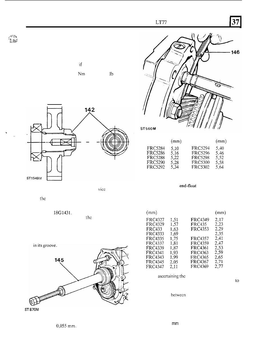
145.  Press 

fit 

fifth 

gear  synchromesh  hub  assembly 

using  tool 

Fit 

a  dummy  spacer with  an 

oversize  bore 

to 

ascertain 

correct  spacer  to 

provide  the specified clearance  on  the  fifth  gear. 
When  fitting,  care  must  be  taken  to  ensure  the 
hub  assembly  and  selective  spacer  are  NOT 

pushed  too  far  on  the  mainshaft.  Only  fit  with 
sufficient  clearance  to  allow  the circlip  to engage 

146.  Measure  t h e   clearance  between  the  front  spaccr 

and  fifth gear  (driven), which  should  be  between 
0,005  and 

Select  the  appropriate 

spacer to provide the aforementioned clearance. 

Part No. 

Thickness  Part 

No. 

Thickness 

147.  Fit the correct selective spacer and new circlip. 

Mainshaft and layshaft 

148. 

Measure  and  adjust  the  mainshaft  and  layshaft 

end-float  as  necessary.  Remove  the  layshaft 
support platc from the front o f  the gearbox. 
Part 

No. 

Thickness  Part No. 

Thickness 

FR C43 

5 5 

149.  When 

mainshaft end-float care must 

be  taken  when  checking  the  dial  gauge  readings 
ensure  that  the  end-float  only,  as  distinct  from  side 
movement, is recorded. 

To 

overcome the difficulty 

in 

differentiating 

end-float and side movement, 

wrap approximately ten  tums of masking tape around 
the plain portion 

of  the input shaft below  the splines. 

Ascertain that the rise and faii of the input 

shaft is not 

restricted by the tape. 

150.  Place  a  mainshaft  and  layshaft  spacer 

of 

nominal 

thickness  1.02 

o n   the  mainshaft  and  layshaft 

bearing  tracks, 

fit 

the  front  cover  and  gasket  tighten 

bolts and spring washers to the specified torque. 

151.  Invert the gearbox on the stand. Rotate the mainshaft 

to correctly seat the bearing. 

13 

FIVE 

SPEED 

GEARBOX 

152. 

153. 

154 

155 

Place  a  suitable  ball  bearing 

in  the  mainshaft 

centre and  mount  the dial  gauge  on  the  gearcase 
with  the  stylus resting 

on  the  ball  bearing centre. 

Zero the gauge. 

Check the  end-float by 

a  'push-pull'  action 

to 

mainshaft.  The  required  mainshaft  end-float 
measurement should be  between 

to 

with no pre-load. 
Spacer  thickness  required  equals;  Nominal 
thickness 

of 

spacer,  plus  end-float  obtained. 

Remove 

t h e  

dial gauge and ball bearing. 

Rotate the  layshaft  to correctly  seat  the bearing. 

Place  a suitable ball  bearing in  the layshaft centre 
and  mount  the  dial  gauge  on  the  gearcase,  with 
the stylus resting on the ball  bearing centre. Zero 
the gauge. 

156. 

157. 

14 

With  the  aid  of  levers approximately 

23 

long; 

to  prevent  component  damage,  check  the 
float  by 

a  gentle  'push-lift'  action  to  the  layshaft. 

The required layshaft setting is: 
0,025 

end-float 

0,025 

preload. 

Spacer  thickness  required 

equals;  nominal 

thickness  of  spacer,  plus  end-float  obtained. 
Remove the gauge and ball bearing. 
Remove the  front  cover.  Having  ascertained  the 

158. 

Fit  a new  oil seal to the front cover, ensuring the 

seal  lips  face  towards  the  gearbox.  Lubricate  the 
scal lips with 

SAE 

140 gear oil. 

159.  Mask  the splines with masking tape to protect 

the 

oil  seal.  refit  the  front  cover  and  remove  the 
spline masking tape. 

160.  Refit  the  bolts  and  spring  washers  having  used 

Hylomar PL32 or Loctitc 290 on the bolt  threads. 

Tighten to 

specified torque. 

161.  Remove  gearbox  from  the  stand  and  place 

suitably  supported  on  the  bench.  Remove  the 
guide studs fitted to the centre plate. 

162.  Select  reverse  gear  by  turning  the  selector  rail 

anti-clockwise  and  pulling  rearwards.  Move  the 
fifth  speed  synchromesh  hub  into 

with  the 

fifth  gear.  Tighten  the  staked  nut  onto  the  fifth 
gear layshaft to the specified torque. Stake the nut 
with  a  suitable 

to secure. Select neutral 

pushing  selector  rail 

inwards  and  turning 

clockwise,  thereby  returning  the  fifth  speed 
synchromesh hub to its out of mesh position. 

Fifth gear selector fork assembly 

163.  Fit the fifth speed selector fork and bracket to 

fifth  gear  synchromesh  hub  assembly, 
that 

largest groove lip 

is facing the rear 

of the 

gearbox. 

164.  Fit the fifth gear spool 

to 

the selector shaft, rotate 

and  engage 

t h e  

selector  fork  into  the 

It 

should  be  noted  that  the  longer  shoulder  of 
spool is fitted towards the front of  the gearbox. 

165.  Fit 

t h e  

fifth  speed sclector  fork 

bolts and 

spring washers.  Tighten to specified torque. 

164 

165 

mainshaft  and layshaft 

the mainshaft 

and  layshaft  spacers of  the  appropriate  thickness 

to  the  mainshaft  and  layshaft  bearing  tracks. 

166.  Fit 

new circlip to the selector shaft ensuring that 

Selective spacers  are available in  a  range 

of  sizes 

it 

is not expanded beyond the minimum necessary 

to meet the aforementioned clearance limits. 

to obtain entry. 

Part No. 

Thickness  Part 

No. 

Thickness 

167.  Remove  the  six  dummy bolts  securing  the  centre 

168.  Position 

gearbox assembly horizontally and fit 

1.81 

2.29 

plate 

the 

the 

oil pump shaft to the pump. 

Extension case 

Fit 

a new gasket to the centre plate. 

170.  Rotate  the  oil  pump  to  align  with  the  oil  pump 

drive shaft. 

LT77 

FIVE SPEED GEARBOX 

171.  Carefully 

fit  the  extension case  ensuring  that  the 

oil pump shaft engages the layshaft. 

172. 

Fit  the 

case  bolts  and  spring  washers; 

tighten to specified torque. 

173.  Using 

a  large  screwdriver, ease the  selector shaft 

forwards  to  selcct  a  gear.  It  may  be  found 

necessary  to  rotate  the  mainshaft  to  ease  gear 
selection. 

174. 

Fit  the  selector  yoke  to  the  selector  shaft  and 

secure  with  a  new 

roll  pin. 

Pull  selector  shaft 

rearwards to select a neutral position. 

175.  Cover  t h e   mainshaft  splines  with  masking  tape 

and fit 

a  new  oil  seal collar 

ring. Remove the 

masking tape. 

176.  Using  tool  1861431 fit  the  oil  seal  collar  to  the 

mainshaft, ensuring t h e  collar 

is NOT pushed  too 

far on  the  shaft, fit  only  with  sufficient  clearance 

to 

allow the circlip to engage 

in its groove. 

177. 

Fit  a  new  gasket  to  the  top  of  the  fifth  gear 
extension  case and 

fit 

the gear change  housing  by 

engaging  male  selector  yoke  with  the  female 
yoke.  Align  the housing locating  dowels and  refit 
the  housing.  Secure  with  the  three  bolts  and 
washers; and tighten  to the specified torque. 

Bell housing 

178.  Locate  the  bell  housing  to  the  dowels  and 

fit 

the 

two long bolts (12 x  45 

with 

spring and plain 

washers  to  the  dowel  positions. 

remaining 

bolts 

(12 

30 mm)  are  fitted  with  spring 

washers only. Tighten to the specified torque. 

1 8 0 b  

179.  Fit  the  clutch  release  lever  pivot  and 

with 

t h e  

bolts  and  spring  washers.  Tighten  to  the 

specified  torque. 

180. 

Prior to reassembly, lubricate t h e  following with a 

thin film of 

disulphide grease: 

(a) 

Clutch release lever fulcrum pivot socket. 

(b) 

clutch  release  lever  slipper pad  pins  and 

(c)  Ball ends of the clutch opcrating push rod. 

181.  Refit  the  slipper  pads  to  the  clutch  release  lever 

and  locate  the  lever  socket  to  the  clutch  release 
lever pivot. 

182.  Lubricate  the  inner  face  of 

clutch 

bearing  carrier  with  molybdenum  disulphide 
grease  and  fit  to  the  front  cover  spigot,  locating 

the clutch release lever slipper pads to  the carrier 
recesses. 

the faces 

of 

pad. 

183.  Fit a 

nylon clutch release carrier clip. 

184.  Refit the gearbox oil level plug, and tighten to the 

Refit  the gearbox  oil  drain  plug  and 

fit 

fibre 

specified torque. 

washer. Tighten plug to specified torque. 

Reverse gear plunger assembly 

186.  Lubricate  the  short  spring  and  plunger 

with 

Energrease 

L2 or similar prior to assembly. 

187.  Fit 

the 

short spring into 

plunger base and slide 

the  assembly  into  the 

gear  plunger 

housing.  Fit  a  new  circlip  to  retain 

t h e  

plunger. 

Ensure  the  spring  is  not  trapped,  the  detent 
groove  should  be  fully  visible  down  the  detent 
hole. 

188.  Lubricate 

the 

detent ball  with  light oil  and 

fit 

into 

its bore. 

189.  Refit  the  long  spring  and  plug,  coat  the  plug 

threads  with  Loctite  290  or  Hylomar 

and 

tighten  to the specified torque. 

The following instructions (190 to 

21 

relate to the early 

model  gearbox  with 

plunger  for  fifth 

gear selection. 

Fifth gear plunger assembly 

Early models only 

Lubricate  the  short  spring  and  plunger  with 

Energrcase L2 

or similar, prior to assembly. 

191. 

Fit 

t h e  

short spring i n  

plunger  base  and  slide 

the  assembly  into the  fifth  gear  plunger  housing. 
Fit  a new circlip to retain  the plunger.  Ensure the 
spring 

is not  trapped, 

t h e  

dctent groove should be 

fully 

down the detent hole. 

192.  Lubricate  the dctent ball  with  light oil  and 

fit 

into 

its bore. 

193.  Refit  the  long  spring  and  plug,  coat  the  plug 

threads  with  Loctite  290  or  Hylomar 
tighten  to the specified torque. 

Gear selector housing 

models 

194.  Refit 

t h e  

gear selector rollers, pin  and new circlip 

ensuring circlip is not  expanded beyond  minimum 

necessary to obtain entry. 

195.  Lubricate  the  gear  selector  housing  shaft 

with 

light 

and 

fit 

a new 

ring. 

15 

LT77 

FIVE SPEED GEARBOX 

196.  Insert  shaft  through  the  large  blanking  plug 

orifice, ensuring the shaft indent is uppermost. 

197.  Place the gear selector housing into protected  vice 

jaws and fit the selector yoke to the shaft, using a 

suitable pin  punch  and  new  roll  pin.  Remove  the 
housing assembly from the vice on completion. 

198.  Fit  the  reverse  switch  and  large  blanking 

plugs. 

Coat plug  threads with  Loctite 290 and tighten  to 

t h e  

specified torque. 

199.  Refit  the 

fifth 

gear  spool  retainer,  coat  the  bolt 

threads with Loctite 290, and tighten the bolts and 
washers to the specified torque. 

200.  Fit  a  new  nylon  insert  into 

trunnion  housing 

and secure with a new circlip. 

201.  Invert  the  gear  sclector  housing  and  fit  the 

trunnion  housing  to  the  selector  shaft,  ensuring 
the locating bolt  aligns with  the shaft indent. Coat 
the  bolt  threads  with  Loctite  290. Tighten  bolt  to 
the specified  torque. 

202.  Fit  a  new  gear  lever  housing  gasket  and  fit  the 

gear  lever  housing,  spring  washers  and  bolts. 
Tighten bolts 

to the specified torque. 

203.  Coat  the  upper  and  lower  balls  of  the  gear  lever 

shaft  with 

Energrease  L2 

or  similar.  Push 

lever into the trunnion nylon  bush. 

204.  Place new vibration  pad over the gear lever and fit 

the  gear  lever  retaining  plate.  Refit  the  three 

shouldered  bolts  and  tighten  to  the  specified 
torque. 

205.  Refit  the  gear  lever  gaiter  and  attach  the  gear 

lever  extension.  Then  carry  out  the  following 
procedure to ensure a clearance of  0,3 to 0,9 
between the gear lever yoke and stops. 

206.  Select  first or second gear. It may  be necessary  to 

rotate  the  mainshaft  whilst  manipulating  the  gcar 
lever. 

reverse gear 

on  the right  hand 

side  viewed  from  the  rear,  giving  sufficient  load 
on  the  trunnion  to  eliminate  side  play.  Whilst 
maintaining  a 

finger  pressure,  measure  the 

clearance  between  the  plunger  assembly  casting 
and  gear  selector  casting.  Add 

0,6 

to  the 

measured  figure  and  select  suitable  thickness 
shims to equal the total. 

16 

208.  Remove  the  reverse  plunger  assembly,  fit  the 

required  thickness 

refit  the  plunger 

assembly,  spring washers and bolts.  ‘Tighten  bolts 
to the specified torque. 

209.  Select third or fourth gear. 
210.  Locate the fifth gear plunger on the  left hand  sidc 

viewed  from the rear, giving Sufficient load o n  the 
trunnion 

to 

eliminate 

sideplay. 

Whilst 

maintaining  a  light  finger  pressure,  measure 
clearance  between  the  plunger  assembly  casting 
and  gear  selector  casting.  Add  0,6 

to  the 

measured  figure  and  select  suitable  thickness 
shims to equal the total. 

211.  Remove  the  fifth  gear  plunger  assembly  and 

fit 

the  required 

refit  the  plunger  assembly, 

spring  washers  and  bolts.  Tighten  bolts  to 

the 

specified  torque. 


Content   ..  69  70  71  72   ..