Defender 90 / 110 / 130. Manual - part 21


  Index      Land Rover     Defender 90 / 110 / 130 - service repair manual


Search            


Content   ..  19  20  21  22   ..


Defender 90 / 110 / 130. Manual - part 21


2.25 LITRE PETROL AND DIESEL ENGINE 

13. 

scored ball valve  seat can be restored  by  using 

locally made lapping tool by  silver soldering a new 
ball  (part  number  3748)  onto  a  length  of  suitable 
tube. 

14.  Install  the  tube 

in  a  drill  and  lap-in  using  coarse 

grinding paste.  Finally  hand-lap  the  seat with 

fine 

paste using the same diabalo method  as 

for lapping 

valves. 

15.  Thorougly  wash  the  pump  body  to  remove  all 

traces of  grinding paste. 

14 

REMOVE  AND  OVERHAUL  THE  TIMING  CHAIN, 
SPROCKETS AND TENSIONER 

1.  Remove  the  timing  cover.  Before  removing  the 

timing  chain  tensioner  notc  the  ratchet  position 

in 

relation  to t h e  pawl  which  will  give  an  indication 

of 

chain wear. If  the last tooth 

of  the ratchet is engaged 

with  the  pawl  t h e   chain 

is  excessively  worn  and 

should be discarded. 

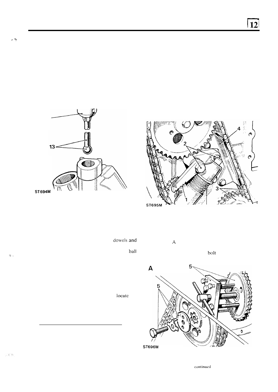
2.  Remove  the  ratchet  pivot  bolt,  plain  bolt  and 

n u t  

and withdraw the timing chain tensioner complete. 

3.  Remove the timing chain and crankshaft sprocket. 
4.  Remove timing chain damper. 

Assemble 

the oil 

pump 

16.  Fit the idler gear to the spindle. 
17. 

Fit  the  driven  gear  with  plain  part  of  the  bore 
uppermost. See illustration  after instruction  9. 

18.  Smear  the  joint  face  of  the  body  with  jointing 

compound  and  fit  the  cover  over  the 
secure with the 

four bolts and spring washers. 

19. 

Hold  relief  valve  bore vertically  and insert the 
followed  by  the plunger with the ball  seat end first. 
Fit the spring, sealing washer and plug. 

20.  Fit  the  oil  strainer  sealing  ring 

to  the 

pump  body 

followed  by  the  lock  washer  and  strainer. Tighten 
the  strainer  retaining  nut 

so  that  when  fitted  the 

strainer  is  positioned  parallel  to  the  sump  baffle 
plate.  Secure  t h e   nut  with  the  lock  washer  tab. 
Later engines are fitted with 

bracket to 

the 

strainer. 

5 .  

Remove  the  camshaft  sprockct  retaining  bolt  and 

washer.  Withdraw  the  sprockct  using  chain  wheel 
extractor 507231 

or similar. 

Illustration 

shows  the  early  retaining  bolt  and  tab 

washer. 
Illustration 

B shows the latest 

and special washer. 

2.25 LITRE PETROL AND DIESEL ENGINE 

REMOVE TAPPETS, ROLLERS AND GUIDES 

6. 

7. 

Examine  the  sprockets  and  discard 

if  the  teeth  are 

worn. 

Dismantle  the  tensioner  assembly  and  discard  any 

worn  parts.  In  particular  check the condition  of  the 
ratchet and pawl.  Check the tension 

of  the spring by 

comparing  it  with  a  new  one.  Examine 

t h e  

jockey 

wheel teeth for wear, and renew bush 

if worn. 

Key 

to tensioner assembly 

1.  Piston assembly 

2.  Cylinder assembly 
3 .   Cylinder spring 
4.  Ball 

5 .  

Ball retaining clip 

6.  Ratchet and spring 
7.  Ratchet pivot bolt 
8.  Pawl 
9.  Jockey wheel 

10. Timing chain damper 

1 .  

2. 

Remove the eight  tappet guide locating bolts from 
the right-hand side of the cylinder block. 

CAUTION: Do not remove the tappet guides before 
the rollers otherwise the 

rollers 

may fall behind the 

camshaft. 

Using long nosed pliers or a suitable bent length of 

wire 

lift 

out the tappet slides and identify them with 

their respective guides for possible refitting. 

3.  Lift  out the tappet rollers and mark  the side facing 

the front of  the engine 

for possible reassembly. 

4. 

Lift  out  the  tappet  guides  and  retain  with  their 

respective  slides  and  rollers. 

If 

the  guides  are 

difficult to remove use special tool 

8.  Assemble  the  tensioner as illustrated  and compress 

the assembly ready for fitting t o  the engine. 

worn or damaged. 

2.25 LITRE PETROL AND DIESEL ENGINE 

RENEW TIMING 

COVER 

OIL SEAL 

On  initial  assembly 

of 

the  engine  the  mud  shield 

around the  oil  seal  is  rivetted  in  position  but  after 
removal 

in 

service  the  rivets  are  substituted  with 

self tapping drive screws. 

2.  Drill out the rivets securing the oil seal mud shield. 

3 .  

Press out the oil seal and clean the mating surfaces. 

4.  Smear the  outside diameter  of  a new  oil  seal  with 

Hylomar P L  

32-M jointing compound.  Press the oil 

seal  into  the  timing  cover,  lip  side  facing 
crankshaft. 

5. 

Coat the drive screws with Hylomar and secure the 

mud shield. 

REMOVE THE CAMSHAFT 

1.  Remove the skew gear bush retaining scrcw and lift 

out  the  skew  gear  bush  assembly. 

Also  withdraw 

the distributor pump (diesel) 

or ignition  distributor 

(petrol  engine)  drive  coupling  with  the  skew 

assembly. 

2.  Since  the  camshaft  sprockct  has  already  been 

removed, bend back  the lock  tabs, remove the  two 
bolts  and  the  camshaft  thrust  plate.  Carefully 
withdraw the camshaft. 

NOTE:  Lock  tab  washers  are  not  used  on  later 
engines 

Inspect the camshaft 

3. 

Discard 

the camshaft 

if  any 

of  the following visual 

defects are evident. 

4.  Scored,  worn,  pitted  or  chipped  cams.  Worn, 

corroded  and  discoloured 

journals.  Worn  and 

chipped gear teeth. 

5 .  

Check  the  journals  for  wear  and 

if  more  than 

0,050 

(0.002 in) the shaft should be renewed. 

6. 

Rest  the  camshaft  between 

'V'  blocks  and  check 

for  run-out  with 

a  dial  indicator.  If  run-out  is  in 

excess 

of 

0,050 

(0.002  in)  the shaft should  be 

straightened 

or renewed. 

2.25 LITRE 

PETROL AND DIESEL ENGINE 

REMOVE AND OVERHAUL 

THE FLYWHEEL 

1. Remove the flywheel retaining  bolts and withdraw 

the flywheel and reinforcing plate. 

2. 

3. 

4. 

Wear 

or scores on 

flywheel clutch  face can be 

corrected  by  machining  provided  that  the  overall 
width  of  the  flywheel  is  not  reduced  below 

the 

following dimensions: 
Petrol engines 

in). 

Diesel engines 

(1.453 in). 

Check  that  the  flywheel  has  not  been  previously 
machined. 
Examine the ring gear teeth and if chipped 

or worn 

the gear can be renewed. 

Reface the flywheel 

5 .  

Remove 

the 

clutch location dowels. 

removing 

only the minimum  material  necessary 

to 

achieve  a  smooth 

flat 

surface  parallel  with  the 

crankshaft  mating face and within  the above width 
dimensions and fit new dowels. 

Renew the ring gear 

7. 

Drill a 

in) hole between the root 

of  any 

two teeth and the inner diameter 

of  the starter ring 

deep enough to weaken the ring. 

Do 

not allow the 

drill to enter the flywheel. 

8. 

Secure the flywheel in a soft jawed vice and cover it 

with 

a  cloth  to  protect  one  from  personal  injury. 

Place a cold chisel above the drilled hole and strike 
it sharply t o  split the ring gear. 

9.  Heat  the  new  ring  gear 

to  between 

and 

but  do  not  exceed  the  higher 

figure. 

10.  Place  the  flywheel,  clutch 

face  down,  on 

flat 

surface  and  locate  the  heated  flywheel  with  the 
square  edge 

of  teeth  downward  towards  the 

flywheel  clutch  face  and  chamfered  edge 

of  the 

teeth  uppermost.  This  applies 

to  both  petrol  and 

Diesel engines. 

11. 

Press the starter ring firmly against the flange until 
the  ring contracts sufficiently 

to  grip the flywheel. 

Allow  the  ring  gear  to  cool  naturally. 

Do  not 

hasten cooling in anyway. 

10 

S T  

928M 


Content   ..  19  20  21  22   ..