Defender 90 / 110 / 130. Manual - part 18


  Index      Land Rover     Defender 90 / 110 / 130 - service repair manual


Search            


Content   ..  16  17  18  19   ..


Defender 90 / 110 / 130. Manual - part 18


MAINTENANCE 

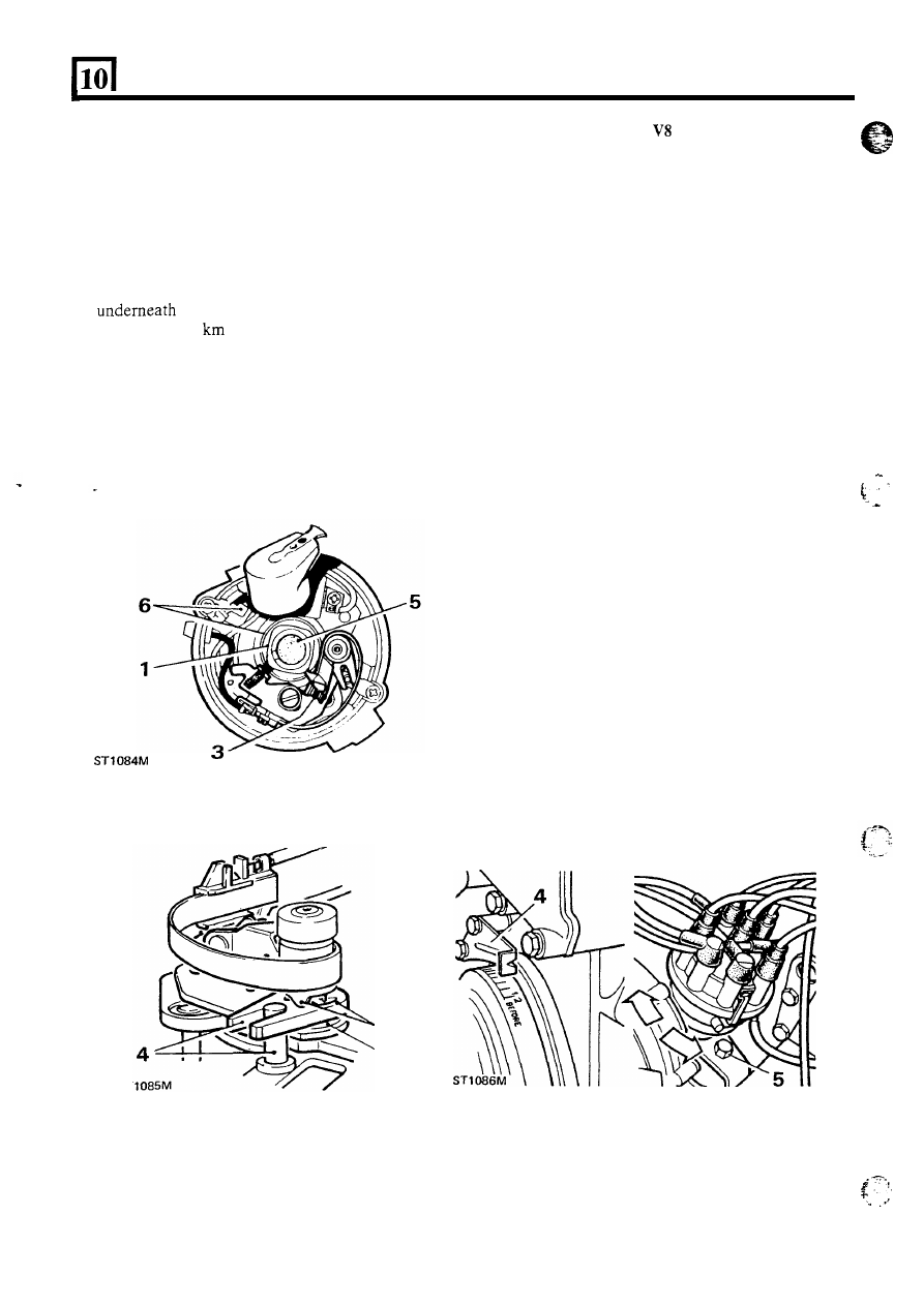
CLEAN AND LUBRICATE LUCAS DISTRIBUTOR 

1.  Clean and lightly grease the cam with Shell Retinax 

o r  equivalent and remove any surplus lubricant. 

2. 

Using  the  same  grease  lubricate  the  underside  of 

the heel actuator. 

3.  Grease  the  actuator  ramps  and  contact  breaker 

heel ribs. 

4.  Apply grease to the fixed pin and the actuator fork. 

5. 

Apply  a  drop 

of  clean  engine  oil  to  the  felt  pad 

the rotor arm. 

6. 

Every 

40.000 

(25,000 

miles)  lubricate  the 

automatic advance  mechanism 

by  injecting one 

or 

two drops 

of  engine oil through the aperture in the 

base plate. 

7.  Wipe  the  internal  and  external  surfaces  of  the 

distributor cap with clean dry nap-free cloth and fit 
the cap to the distributor body. 

ST 

CHECK  AND  ADJUST 

ENGINE  DISTRIBUTOR 

TIMING 

Using Electronic Timing Equipment 

A  pointer  on  the  timing  cover  and  marks  on  the 

crankshaft  pulley  indicate positions around 

T.D.C. 

on 

No. 

1  cylinder  (i.e.  front cylinder on left-hand  bank). 

Refer to  'Engine  Tuning data'  for appropriate ignition 
timing. 

Engine  speed  accuracy  during  ignition  timing 

is 

important.  Any variation from the required idle speed, 
particularly in an upward direction, will lead to wrongly 
set ignition timing. 

1.  Connect a stroboscopic timing light as instructed by 

the  manufacturer.  The  engine  is  timed  on 

No.  1 

cylinder. 

2 .   Run the engine at idle speed. 
3.  Position  the  timing  light  to  illuminate  the 

crankshaft pulley and scale. 

WARNING:  Ensure that  personnel and equipment 
are kept clear of the rotating cooling fan while using 

the 

timing light. 

4.  If  the timing is correct the pulley mark indicated  in 

the Tuning Data will show. If  correct, instruction 

may be ignored. 

5. 

With the engine still running at idle speed, slacken 
the clamp bolt  and  carefully  rotate  the  distributor 

body  as  required  until  the  correct  pulley  mark 
shows.  Turn  anticlockwise  to  advance  and 

clockwise to retard. 

6.  Tighten  the  clamp  bolt  with  the  unit  in  this 

position. 

20 

MAINTENANCE 

CLEAN, ADJUST 

OR 

RENEW SPARK PLUGS 

Refit or renew spark plugs 

1.  Withdraw  the 

H.T. 

leads from the  spark  plugs  by 

2.  Using  an  appropriate  plug  spanner,  remove  the 

gripping the shrouds, do not pull on the leads. 

spark plugs. 

11. 

Check that the washers are fitted to the plugs. 

12.  It 

important  that  only  spark  plugs  specified  in 

Data section are used for replacements. 

13.  Incorrect  grades 

of plug  may  lead  to  piston  over- 

heating and engine failure. 

14.  Wash new plugs in petrol to remove the protective 

coating,  then  set  the  electrode  gaps  to  the 
appropriate figures given in ‘Engine Tuning data’. 

15. 

Fit  the plugs  and washers to the engine but  do not 

overtighten. 

16.  Examine  high  tension  leads,  including  the  coil  to 

distributor  lead,  for  insulation  cracking  or 
corrosion  at  end  contacts.  Fit  new  leads  as 
necessary. 

17.  In  addition  to  correct  firing  order,  high  tension 

leads  must  be  fitted  in  correct  relation  to  each 
other  to  avoid  cross  firing,  as  illustrated.  This  is 
particularly important on the V8 engine. 

First illustration. 4-cylinder engine. 
Second illustration. 

engine. 

shrouds are firmly seated on plugs. 

Clean and set gaps 

18.  When pushing leads on plugs ensure ferrules within 

3. 

Fit plug in plug cleaning machine. 

4.  Wobble plug  with  circular motion  while  operating 

abrasive blast for 

a maximum of four seconds. 

CAUTION:  Excessive  abrasive  blasting will  erode 

insulator nose. 

5.  Change  to  air  blast  only  and  continue  to wobble 

plug  for  a  minimum  of  thirty  seconds  to  remove 
abrasive grit from plug cavity. 

6.  Wire-brush plug threads, open gap slightly. 
7.  Using point file, square off electrode surfaces. 
8.  Set electrode gap, 

see ‘Engine Tuning data’, 

9. 

Test  plugs  in  accordance  with  cleaning  machine 
manufacturer’s  instructions.  If  satisfactory,  refit 
plugs in engine. 

10. 

If  no  machine  is  available  carefully  wire  brush 

electrodes and blow or wash away carbon particles. 

Illustration shows: 

A. 

Dirty o r  unsatisfactory electrode 

Filing plug electrodes 

C. 

clean 

plug correctly set 

21 

MAINTENANCE 

CLEAN 

AND  TEST  HEATER  PLUGS 

Diesel 

CHECK BRAKE FLUID RESERVOIR 

engines 

REMOVE THE PLUGS 

1. Check  the  fluid  level  in  the  fluid  reservoir  by 

observing  the  level  in  relation  to  the 

or 

‘MAX’ 

marks  on  the  side  of  the  translucent 

reservoir. 

2.  If  the  level  is  below  the 

‘MAX’ 

mark  clean  the 

outside of  the filler cap and top-up with new, clean 
fluid  from  a  sealed  container.  Use  only  fluid 
recommended  in  the  ‘General  specification  data’ 
section. Refit the cap. 

1.  Disconnect the battery. 

2.  Remove the terminal nut from each heater plug. 

3 .  

Detach the heater plug lead  and washer  from each 

4. 

Remove the heater plugs. 

Clean and inspect 

5. 

Remove carbon from base of  heater plugs to avoid 
the  possibility  of  short  circuiting 

of  the  element. 

Do not sandblast. 

6. 

Examine  the  element  for  signs  of  fracture  and 
deterioration and the seating for scores. Plugs with 

fractures  or  doubtful  elements  must  be  renewed. 
Where  scoring  of  the  seating  may  impair  the 

sealing, the plug should be renewed. 

Test and refit 

7. 

Test  the  plug  internal  circuit  for  continuity  by 
connecting it in circuit with a 12 volt side lamp bulb 

open circuit  is  indicated  and  the  heater  plug  must 
be renewed. 

and  a  12 volt  supply. If  the  bulb  does not  light  an 

ST 1088M 

8.  Ensure  that  the  terminals  are  clean  and  that  the 

thread at the base 

of  the plug is free from carbon. 

9.  Fit  the  heater  plugs  to  the  engine. 

Do 

not 

overtigh ten. 

10. 

Fit the heater plug lead and washer to each plug. 

11. 

Connect the battery. 

CHECK CLUTCH FLUID RESERVOIR 

1.  Clean  and  remove  the  reservoir  cap  and  observe 

the fluid level 

in relation to the marks 

on the side of 

the reservoir. 

2.  Top-up if  necessary  with  new,  clean  fluid  from  a 

sealed 

container 

and 

of 

recommended 

specification 

see  ‘General  specification  data’ 

section. Refit the cap. 

22 

,

I

-


CHECK POWER STEERING 

FLUID RESERVOIR 

..... 

.. 

1.  Clean  and  remove  the  reservoir  cap  and  observe 

the fluid level 

in 

relation  to the mark 

on 

the side of 

the reservoir. 

2.  If  necessary  top-up with  a  recommended  fluid 

see ‘General specification  data’ section 

until the 

fluid  is  12 

in)  above  the  filter.  Refit  the 

cap. 

CHECK 

COOLING SYSTEM COOLANT 

Refer  to  the  ‘Cooling  system’  section  for  details 

of 

anti-freeze  and  inhibitors  and  to  the  ‘General 

specification  data’  section  for  anti-freeze  protection 
quantities. 
With  a  cold  engine,  the  expansion  tank  should  be 
approximately half full. 

WARNING: 

Do  not  remove  the  filler  cap  when  the 

engine  is  hot  because  the  cooling  system is  pressurised 
and personal scalding could result. 

To remove the filler cap, first turn it anti-clockwise 
a quarter of a turn and allow all pressure  to escape, 
before turning further in the same direction to lift it 

off. 
When replacing the 

cap it is  important  that it 

is  tightened  down 

not  just  to  the  first  stop. 

Failure to tighten the filler cap properly  may result 
in  water  loss, with  possible  damage  to  the  engine 
through overheating. 

MAINTENANCE 

BATTERY 
Check Specific Gravity 

T h e   specific  gravity  of  the  electrolyte  should  be 
checked  using  a  battery  hydrometer.  The  readings 
should be as follows: 
Temperate 

climate 

below 

(80°F) 

as 

commissioned  for service,  fully charged  1.270 to 1.290 
specific gravity. 
As  expected  during  normal  service,  three-quarter 
charged  1.230 to 

1.250 specific gravity. 

If  the  specific  gravity  should  read  between  1.190  to 
1.210, half-charged, the battery must be bench charged 
and  the  electrical  equipment  in  the  car  should  be 

checked. 

Tropical climate above 

(80°F) as commissioned 

for service, fully charged  1.210 to 1.230 specific gravity. 
As  expected  during  normal  service,  three-quarter 
charge 1.170 to 1.190 specific gravity. 
If  the  specific  gravity  should  read  between  1.130  to 

half-charged,  the battery must be bench charged 

and  the  electrical  equipment 

on  the  car  should  be 

checked. 
Check and Top-Up Electrolyte Level 

1.  Wipe all dirt and moisture from the battery top. 

2.  Remove the filler cover. If  necessary add sufficient 

distilled  water  to  raise  the  level  to  the  top 

of 

separators. 
Replace the filler plugs or manifold lid. 

3 .  Avoid the use of  a naked light when examining the 

4.  In  hot  climates  it  will  be  necessary  to  top  up  the 

battery at more frequent intervals. 

5 .  

In very  cold weather it is essential  that  the vehicle 

is used immediately after topping up, to ensure that 
the  distilled  water  is  thoroughly  mixed  with  the 
electrolyte. Neglect of this precaution may result in 
the distilled  water  freezing  and causing damage to 
the battery. 

Battery terminals 

6 .  Remove battery terminals, clean, grease and refit. 

7 .  

Replace  terminal  screw;  d o   not  overtighten. 

Do 

not use the screw for pulling down the terminal. 

8.  Do 

N O T   disconnect  the  battery  cables  while  the 

engine  is  running  or  damage  to  alternator 
semiconductor  devices  may  occur.  It 

also 

inadvisable 

to 

break or make any connection 

in the 

alternator  charging  and  control  circuits  while  the 
engine is running. 

9.  It is essential to observe the polarity of connections 

to  the  battery,  alternator  and  regulator,  as  any 
incorrect  connections  made  when  reconnecting 

cables  may  cause  irreparable  damage  to  the 
semiconducto  devices. 

IMPORTANT NOTE:  If  a  new  battery is  fitted 

the 

vehicle,  it should be the same type as fitted to the vehicle 
when  new.  Alternative  batteries  may  vary  in  size 

and 

terminal  positions  and  this  could  be  a  possible  fire 
hazard  if  the terminals or leads come into contact with 
the battery clamp assembly. When fitting a new battery 
ensure  that  the  terminals  and  leads  are  clear  of  the 
battery clamp assembly. 


Content   ..  16  17  18  19   ..