Index Land Rover Defender - service manual 1999-2002 year
Search
Content .. 112 113 114 115 ..
Defender (1999-2002). Manual - part 114
77
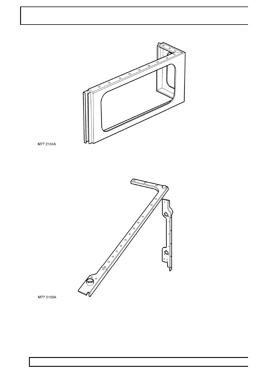
PANEL REPAIRS
4
PANELS
12. Body side rear - upper
13. Body side cappings