Defender (1999-2002). Manual - part 70


  Index      Land Rover     Defender - service manual 1999-2002 year


Search            


Content   ..  68  69  70  71   ..


Defender (1999-2002). Manual - part 70


30

MANIFOLD AND EXHAUST SYSTEM

2

REPAIR

Refit

12. Clean front pipe and mating faces.
13. Position front pipe and using new gaskets, align

to intermediate pipe and turbocharger.

14. Connect mounting rubber to front pipe.
15. Fit and tighten exhaust flange nuts to 27 Nm (20

lbf.ft) .

16. Fit chassis cross member, and tighten bolts to

45 Nm (33 lbf.ft)

17. Fit underbelly panel. See CHASSIS AND

BODY, Repair.

18. Position new gasket and front pipe to

turbocharger and tighten nuts to 27 Nm (20
lbf.ft).

19. Position exhaust manifold heat shield and

tighten M6 bolts to 10 Nm (7 lbf.ft) and M8 bolt
to 25 Nm(18 lbf.ft) .

20. Position air inlet hose to turbocharger and

tighten clip screw.

21. Connect air flow meter to air filter and secure

clips.

22. Connect air flow meter multiplug.
23. Connect breather hose and secure clip.
24. Fit engine acoustic cover. See ENGINE ,

Repair.

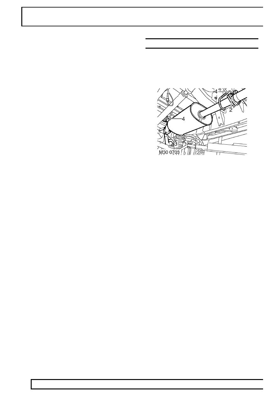
SILENCER - INTERMEDIATE

Service repair no - 30.10.11

Remove

1. Raise vehicle on a 4 post ramp.

2. Remove 2 nuts securing intermediate silencer to

front pipe.

3. Remove 3 nuts securing intermediate silencer to

tail pipe.

4. Release intermediate silencer from rubber

mountings and remove silencer.

5. Remove and discard gasket from tail pipe flange.

Refit

6. Clean intermediate silencer and mating faces.
7. Fit new gasket to tail pipe flange.
8. Position intermediate silencer to rubber

mountings and tail pipe flange.

9. Fit nuts securing intermediate silencer to front

pipe and tail pipe and tighten to 25 Nm (18
lbf.ft).

MANIFOLD AND EXHAUST SYSTEM

3

REPAIR

EXHAUST - TAIL PIPE AND SILENCER

Service repair no - 30.10.22

Remove

1. Raise vehicle on ramp.

2. Remove 3 nuts securing silencer to tail pipe.
3. Release tail pipe from mounting and remove tail

pipe.

4. Collect silencer to tail pipe gasket.

Refit

5. Clean silencer and tail pipe mating faces.
6. Position tail pipe and secure on mounting

rubber.

7. Using a new gasket, align silencer to tail pipe.
8. Fit nuts to silencer and tighten to 25 Nm (18

lbf.ft).

GASKET - INLET MANIFOLD

Service repair no - 30.15.08

Remove

1. Remove battery cover.
2. Disconnect battery negative lead.
3. Remove 3 bolts and remove engine acoustic

cover.

4. Release retainers and remove cooling fan cowl.

5. Disconnect multiplug from manifold air pressure

sensor and release 4 glow plug leads.

6. Remove 4 bolts, release EGR valve from inlet

manifold and discard gasket.

30

MANIFOLD AND EXHAUST SYSTEM

4

REPAIR

7. Remove 4 bolts securing fuel cooler to inlet

manifold.

8. Remove 2 bolts and remove alternator support

bracket and disconnect fuel injector harness
multiplug.

9. Remove bolt securing engine dip stick tube to

camshaft carrier.

10. Remove dip stick tube and discard ’O’ ring.

11. Remove 2 nuts and 8 bolts securing inlet

manifold to cylinder head.

12. Disconnect multiplugs from turbocharger boost

control soleniod, ECT sensor, ambient air
pressure sensor, MAF sensor, and A/C
compressor.

NOTE: EU3 Model illustrated.

13. Remove 2 bolts securing harness to camshaft

carrier.

14. Release harness from engine and inlet manifold.
15. Remove inlet manifold and gasket.

MANIFOLD AND EXHAUST SYSTEM

5

REPAIR

Refit

16. Clean inlet manifold and mating face.
17. Fit new gasket.
18. Fit inlet manifold, and working from the centre

outwards, tighten nuts and bolts to 25 Nm (18
lbf.ft).

19. Position harness to sensors and connect

multiplugs.

20. Tighten harness clip bolts to camshaft carrier to

10 Nm (7 lbf.ft).

21. Clean dip stick tube and fit new ’O’ ring.
22. Fit dip stick tube and tighten bolt to 10 Nm (7

lbf.ft).

23. Connect glow plug leads.
24. Fit alternator support bracket and tighten bolts to

45 Nm (33 lbf.ft).

25. Position fuel cooler. Apply Loctite 242 to bolts

and tighten to 18 Nm (13 lbf.ft).

26. Fit new gasket, position EGR valve and tighten

bolts to 9 Nm (7 lbf.ft).

27. Connect multiplug to MAP sensor.
28. Fit cooling fan cowl.
29. Fit engine acoustic cover.
30. Reconnect battery negative lead.
31. Fit battery cover.

GASKET - EXHAUST MANIFOLD

Service repair no - 30.15.12

Remove

1. Remove turbocharger. See FUEL SYSTEM,

Repair.

2. Models with A/C: Remove auxiliary drive belt.

See ELECTRICAL, Repair.

3. Remove 4 bolts securing compressor and move

to one side.
All Models

NOTE: EU3 Model illustrated.

4. Remove and discard 2 Allen screws securing

EGR pipe to exhaust manifold.

5. Remove 10 nuts securing exhaust manifold to

cylinder head.

6. Remove exhaust manifold and gasket.


Content   ..  68  69  70  71   ..