Defender (1999-2002). Manual - part 42


  Index      Land Rover     Defender - service manual 1999-2002 year


Search            


Content   ..  40  41  42  43   ..


Defender (1999-2002). Manual - part 42


ENGINE

25

OVERHAUL

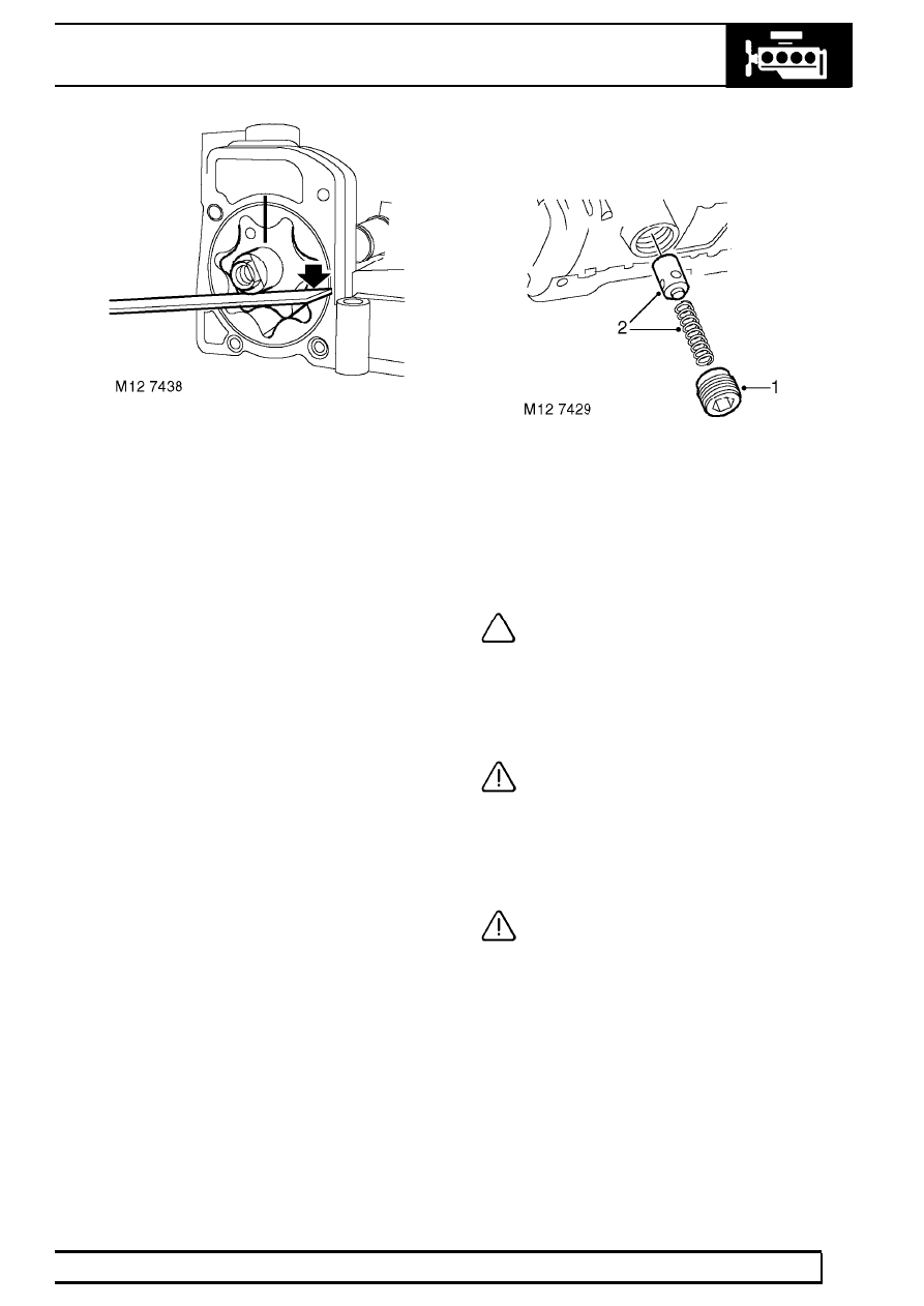
8. Place a straight edge across pump body and

using feeler gauges, measure end-float of outer
rotor:
Outer rotor end-float = 0.038 to 0.075 mm
(0.001 to 0.003 in)

9. Check drive shaft bush in pump cover for signs

of scoring and wear.

10. Renew oil pump and stiffener plate assembly if

excessive scoring exists or clearances exceed
limits given.

11. Lubricate pump rotors and drive shaft bush with

engine oil.

12. Fit rotors ensuring reference marks are aligned

and identification mark on inner rotor is facing
forwards.

13. Fit cover to pump, fit 5 new screws and tighten

by diagonal selection to 6 Nm (4.5 lbf.ft) .

14. Check that pump rotors rotate freely.

Oil pressure relief valve

1. Remove and discard oil pressure relief valve

plug.

2. Remove spring and relief valve plunger.
3. Clean valve plunger and spring.
4. Check valve plunger and relief valve bore for

scoring and corrosion.

NOTE: Light scoring and corrosion may be
removed using grade 600 emery cloth
soaked in oil.

5. Check spring for distortion, check free length of

spring:
Spring free length = 42.00 mm (1.65 in)

CAUTION: Renew relief valve as an
assembly.

6. Lubricate valve plunger and seating.
7. Fit valve plunger and spring to oil pump.
8. Apply Loctite 243 sealant to threads of a new

plug.

CAUTION: Do not attempt to fit original
plug.

9. Fit plug and tighten to 23 Nm (17 lbf.ft) .

12

ENGINE

26

OVERHAUL

Refit

1. Clean mating faces of oil pump, stiffener plate

assembly and cylinder block; ensure bolt and
dowel holes are clean and dry.

2. Lubricate a new ’O’ ring with engine oil and fit to

oil pump housing outlet.

3. Position oil pump and stiffener plate assembly

on to cylinder block ensuring 2 dowels are
correctly located.

4. Fit new bolts and using sequence shown, tighten

to 13 Nm (10 lbf.ft) .

5. Lubricate a new ’O’ ring with engine oil and fit to

oil pick-up strainer.

6. Clean threads of oil pick-up strainer Torx screws

and apply Loctite 242 to threads.

7. Fit oil pick-up strainer, fit Torx screws and

tighten to 10 Nm (8 lbf.ft) .

8. Position oil pump drive sprocket to chain and oil

pump ensuring that the ’D’ shape on the drive
sprocket is located on the flat on the oil pump
drive shaft.

9. Clean threads of oil pump drive sprocket

retaining bolt and apply Loctite 242 to threads.

10. Fit oil pump drive sprocket bolt and tighten to 25

Nm (18 lbf.ft) .

11. Fit sump gasket. See this Section.

TIMING CHAIN AND SPROCKETS

Service repair no - 12.65.13.01

Remove

1. Remove cylinder head gasket. See this

Section.

CAUTION: If timing chain tensioner is to
be replaced, ensure tensioner is correct
for engine. Tensioner bodies are colour

coded as follows:- Engine Serial No. Prefixes 10P
to 14P - BLACK with, additionally, on later
engines, YELLOW on tensioner hex. head. Engine
Serial No. Prefixes 15P to 19P:- Body is coloured
YELLOW. Later tensioners may be fitted to early
engines provided that the modified adjustable
guide is also fitted.

2. Remove 3 bolts securing crankshaft damper to

pulley, remove damper.

3. Position LRT-51-003 to crankshaft pulley and

secure with 2 bolts.

4. Using assistance, restrain engine and remove

crankshaft pulley bolt; discard bolt.

WARNING: CRANKSHAFT BOLT IS
TIGHTENED TO 460 Nm (340 lbf.ft),
ENSURE THAT ENGINE IS ADEQUATELY

RESTRAINED.

5. Remove crankshaft pulley, remove bolts and

tool.

6. Remove sump gasket. See this Section.

ENGINE

27

OVERHAUL

7. Noting their fitted positions, remove 8 bolts

securing timing chain cover.

8. Remove timing chain cover.

NOTE: Dowel located.

9. Remove bolt securing oil pump drive sprocket.

10. Remove oil pump drive sprocket.
11. Remove camshaft and crankshaft sprockets

together with timing and oil pump drive chains.

12. Remove Woodruff key from crankshaft.

13. Remove 2 bolts and remove timing chain fixed

guide.

14. Remove bolt and remove timing chain adjustable

guide.

15. Remove bolt and remove timing chain lubrication

jet.

16. Using tool LRT-12-092, remove and discard oil

seal from timing cover.

12

ENGINE

28

OVERHAUL

Inspection

1. Clean all components.
2. Check condition of timing chain running surfaces

on adjustable and fixed guides.

CAUTION: Adjustable guide fitted to
Engine Serial No. Prefixes 15P to 19P may
be fitted to Engine Serial No. Prefixes 10P

to 14P provided that timing chain tensioner having
a YELLOW colour coded body is also fitted.

3. Check timing chains and sprockets for signs of

wear.

CAUTION: Timing chains and sprockets
fitted to Engine Serial No. Prefixes 15P to
19P may be fitted to Engine Serial No.

Prefixes 10P to 14P as an assembly only, oil pump
sprockets are interchangeable. Timing chains
fitted to Engine Serial No. Prefixes 15P to 19P
have BRONZE coloured timing links.

4. Check that drilling in timing chain lubrication jet

is clear.

5. Clean oil seal recess in timing cover and oil seal

running surface on crankshaft.

6. Remove all traces of sealant from mating faces

of timing cover and cylinder block using suitable
solvent.

CAUTION: Do not use metal scrapers.

7. Ensure bolt and dowel holes are clean and dry.
8. Clean oil pump sprocket bolt threads.

Refit

1. Fit timing chain lubrication jet.
2. Fit bolt securing lubrication jet and tighten to 10

Nm (7 lbf.ft).

3. If crankshaft has been rotated, check that No. 1

piston is at TDC using the following procedures:

4. Temporarily fit and lightly tighten a new

crankshaft pulley bolt.

5. Assemble a magnetic base DTI to cylinder block

top face, position stylus to cylinder block top face
and zero gauge.

6. Using crankshaft pulley bolt, rotate crankshaft

clockwise until No. 1 piston is at top of its stroke
and Woodruff key slot in crankshaft is at 12
o’clock position.

7. Position stylus of DTI to No. 1 piston crown and

rotate crankshaft until highest reading is
indicated on DTI.

8. Check that Woodruff key slot in crankshaft is still

at 12 o’clock position indicating No. 1 piston is at
TDC firing.

9. Remove DTI.


Content   ..  40  41  42  43   ..