Defender (1999-2002). Manual - part 32


  Index      Land Rover     Defender - service manual 1999-2002 year


Search            


Content   ..  30  31  32  33   ..


Defender (1999-2002). Manual - part 32


ENGINE

19

REPAIR

70. Connect coolant hoses to fuel cooler and coolant

rail and secure clips.

71. Fit air intake hose to intake elbow and tighten

clip screw.

72. Fit starter motor. See ELECTRICAL, Repair.
73. Fit turbocharger. See FUEL SYSTEM, Repair.
74. Fit radiator. See COOLING SYSTEM, Repair.
75. Fit air filter. See FUEL SYSTEM, Repair.
76. Fill engine with oil.
77. Fit underbelly panel. See CHASSIS AND

BODY, Repair.

MOUNTING - FRONT - LH

Service repair no - 12.45.01

Remove

1. Remove centrifuge assembly. See this

Section.

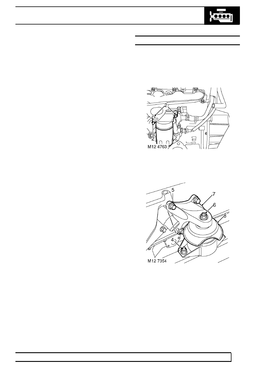
2. Remove 3 bolts, remove oil filter adaptor

housing and discard gasket.

3. Fit suitable lifting chains to support engine.

4. Remove 2 nuts securing engine mounting to

chassis.

5. Remove 4 bolts securing engine mounting

bracket to cylinder block.

6. Remove nut securing mounting to mounting

bracket.

7. Remove mounting and mounting bracket.
8. Remove mounting shield.

12

ENGINE

20

REPAIR

Refit

9. Fit shield to mounting ensuring cut-away portion

is correctly aligned.

10. Fit mounting and mounting bracket.
11. Fit mounting bracket to cylinder block bolts and

tighten to 48 Nm (35 lbf.ft) .

12. Fit nuts securing mounting to chassis and tighten

to 85 Nm (63 lbf.ft) .

13. Fit mounting to mounting bracket nut and tighten

to 85 Nm (63 lbf.ft) .

14. Remove engine support chains.
15. Clean oil filter adaptor housing and mating face.
16. Fit oil filter adaptor housing using a new gasket

and tighten bolts to 25 Nm (18 lbf.ft) .

17. Fit centrifuge assembly. See this Section.

MOUNTING - FRONT - RH

Service repair no - 12.45.03

Remove

1. Remove engine acoustic cover. See this

Section.

2. Remove fixings, remove battery cover.
3. Disconnect battery negative lead.
4. Raise front of vehicle.

WARNING: Support on safety stands.

5. Remove 4 bolts, move fuel cooler to one side.
6. Fit suitable lifting chains to support engine.

7. Remove 2 nuts securing engine mounting to

chassis.

8. Remove 4 bolts securing engine mounting

bracket to cylinder block.

9. Remove nut securing mounting to mounting

bracket.

10. Remove mounting and mounting bracket.

ENGINE

21

REPAIR

Refit

11. Fit mounting and mounting bracket.
12. Fit mounting bracket to cylinder block bolts and

tighten to 48 Nm (35 lbf.ft) .

13. Fit nuts securing mounting to chassis and tighten

to 85 Nm (63 lbf. ft).

14. Fit mounting to mounting bracket nut and tighten

to 85 Nm (63 lbf.ft) .

15. Remove engine support chains.
16. Position fuel cooler. Apply Loctite 242 to bolts

and tighten to 18 Nm (13 lbf.ft).

17. Remove stand(s) and lower vehicle.
18. Reconnect battery negative lead.
19. Fit engine acoustic cover. See this Section.

MOUNTING - GEARBOX - REAR - LH

Service repair no - 12.45.07

Remove

1. Raise vehicle on ramp.
2. Position jack to support gearbox.

3. Remove 4 bolts securing mounting bracket to

transfer gearbox.

4. Remove 2 nuts, remove mounting and mounting

bracket.

5. Remove heat shield from mounting.

Refit

6. Clean mounting and mating faces.
7. Position heat shield to mounting.
8. Position mounting and mounting bracket and

tighten nuts to 48 Nm (35 lbf.ft) and bolts to 85
Nm (63 lbf. ft).

9. Lower support jack.

10. Lower vehicle.

12

ENGINE

22

REPAIR

MOUNTING - GEARBOX - REAR - RH

Service repair no - 12.45.09

Remove

1. Remove LH rear gearbox mounting. See this

Section.

2. Remove 4 bolts securing mounting bracket to

transfer gearbox.

3. Remove 2 nuts, remove mounting and mounting

bracket.

Refit

4. Clean mounting and mating faces.
5. Position mounting and mounting bracket and

tighten nuts to 48 Nm (35 lbf.ft) and bolts to 85
Nm (63 lbf.ft).

6. Fit LH rear gearbox mounting. See this

Section.

FLYWHEEL

Service repair no - 12.53.07

Remove

1. Remove clutch assembly. See CLUTCH,

Repair.

2. Remove and discard 8 bolts securing flywheel to

crankshaft and remove flywheel.

NOTE: Dowel located.

Refit

3. Clean flywheel and crankshaft mating face.
4. Position flywheel to crankshaft.
5. Fit new flywheel retaining bolts and tighten by

diagonal selection to:
Stage 1 - 40 Nm (30 lbf.ft)
Stage 2 - Further 90

°

CAUTION: Do not carry out stages 1 and 2
in one operation.

6. Fit clutch assembly. See CLUTCH, Repair.


Content   ..  30  31  32  33   ..