Defender (1999-2002). Manual - part 28


  Index      Land Rover     Defender - service manual 1999-2002 year


Search            


Content   ..  26  27  28  29   ..


Defender (1999-2002). Manual - part 28


ENGINE

3

REPAIR

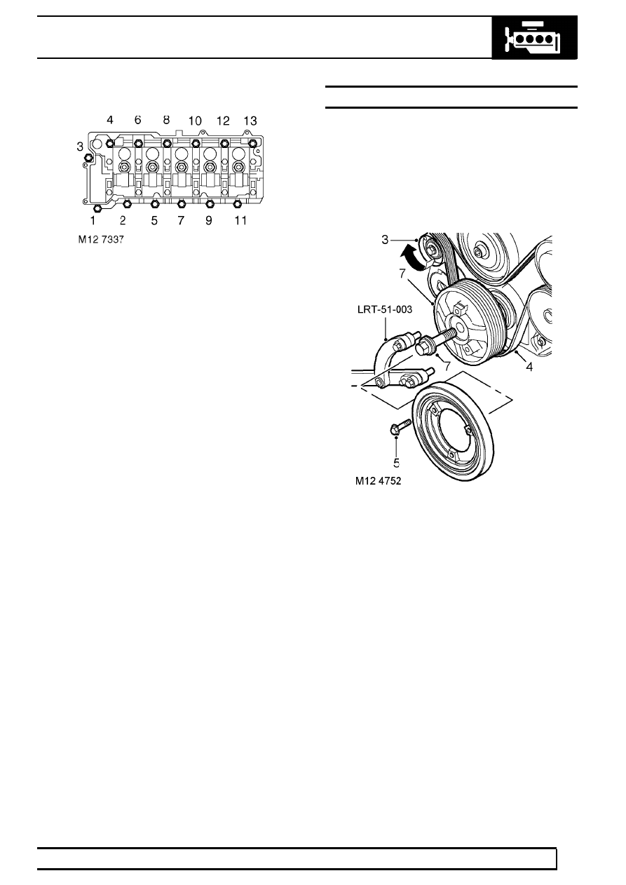
25. Using sequence shown, progressively tighten

bolts to 25 Nm (18 lbf.ft).

26. Lubricate a new camshaft rear oil seal with

engine oil, fit seal using a suitable mandrel.

27. Fit rocker shaft ensuring it is located on dowel, fit

new bolts and working from the centre outwards,
tighten bolts progressively to 32 Nm (24 lbf.ft).

28. Fit new ’O’ ring to injector harness multiplug, fit

harness and connect injector multiplugs.

29. Fit cylinder head gasket. See this Section.
30. Before refitting the camshaft cover the fuel

injector rockers must be adjusted.

31. Rotate engine clockwise until No. 1 injector lobe

is at full lift.

32. Rotate rocker adjusting screw clockwise until the

injector plunger is felt to bottom out.

33. Rotate rocker adjusting screw anti-clockwise 1

complete turn to give plunger the required bump
clearance and tighten rocker adjusting screw
locknut to 16 Nm (12 lbf.ft) .

34. Carry out above procedure for the remaining 4

rockers.

35. After completion of rocker adjustment, slowly

rotate engine clockwise 2 complete turns by
hand to ensure that no injectors are bottoming
out on their plungers.

PULLEY - CRANKSHAFT

Service repair no - 12.21.01

Remove

1. Remove underbelly panel. See CHASSIS AND

BODY, Repair.

2. Remove radiator. See COOLING SYSTEM,

Repair.

3. Using a 15 mm ring spanner release the

auxiliary drive belt tensioner.

4. Remove auxiliary drive belt.
5. Remove 3 bolts and remove crankshaft damper.
6. Position LRT-51-003 to crankshaft pulley and

secure with 2 bolts.

7. Remove and discard crankshaft pulley bolt.

Remove crankshaft pulley.

8. Remove 2 bolts and remove LRT-51-003 .

12

ENGINE

4

REPAIR

Refit

9. Position new crankshaft pulley to vice.

10. Remove 3 bolts and remove damper from

crankshaft pulley.

11. Using a lint free cloth, thoroughly clean oil seal

recess and the running surface on crankshaft
pulley.

12. Fit crankshaft pulley.
13. Fit LRT-51-003 to crankshaft pulley and secure

with 2 bolts.

14. Fit new crankshaft pulley bolt and tighten to 460

Nm (340 lbf.ft).

NOTE: It is recommended that a torque
multiplier is used to tighten crankshaft
pulley bolt.

15. Remove 2 bolts and remove LRT-51-003 from

crankshaft pulley.

16. Fit damper to crankshaft pulley, fit bolts and

tighten to 80 Nm (60 lbf.ft) .

17. Fit auxiliary drive belt.
18. Fit radiator. See COOLING SYSTEM, Repair.
19. Fit underbelly panel. See CHASSIS AND

BODY, Repair.

OIL SEAL - CRANKSHAFT - REAR

Service repair no - 12.21.20

Remove

1. Remove flywheel. See this Section.
2. Remove sump gasket. See this Section.

3. Remove 5 bolts securing oil seal housing to

cylinder block.

4. Remove seal housing.

Refit

5. Clean seal housing mating face on cylinder

block.

6. Position seal protector, LRT-12-061 over

crankshaft boss. Fit new seal and housing
assembly and remove tool LRT-12-061.

CAUTION: Oil seal must be fitted dry.

ENGINE

5

REPAIR

7. Fit oil seal housing bolts and using sequence

shown, tighten to 9 Nm (7 lbf.ft).

8. Fit sump gasket. See this Section.
9. Fit flywheel. See this Section.

BEARING - SPIGOT - CRANKSHAFT

Service repair no - 12.21.45

Remove

1. Remove clutch assembly. See CLUTCH,

Repair.

2. Tap a thread in spigot bush to accommodate a

suitable impulse extractor.

3. Fit extractor to spigot bush.
4. Remove spigot bush from crankshaft.

Refit

5. Clean spigot bush and mating face in rear of

crankshaft.

6. Fit new spigot bush to crankshaft using a

suitable drift.

7. Fit clutch assembly. See CLUTCH, Repair.

12

ENGINE

6

REPAIR

GASKET - CYLINDER HEAD

Service repair no - 12.29.02

Remove

NOTE: The following procedures cover
engines fitted with or without an EGR
cooler. The EGR cooler is bolted to the

front of the cylinder head.

1. Remove underbelly panel. See CHASSIS AND

BODY, Repair.

2. Drain cooling system. See COOLING

SYSTEM, Adjustment.

3. Remove camshaft cover gasket. See this

Section.

4. Remove cooling fan. See COOLING SYSTEM,

Repair.

5. Release clips and disconnect air flow meter from

air filter.

6. Disconnect multiplug from air flow meter.
7. Loosen clip and remove air inlet hose from

turbocharger.

8. Remove 3 bolts and remove exhaust manifold

heat shield.

9. Remove turbocharger oil feed banjo bolt and

discard sealing washers.

10. Remove 3 nuts, release turbocharger from

exhaust manifold, discard gasket and tie
turbocharger aside.

11. Remove 2 bolts securing engine harness to

camshaft carrier.

12. Disconnect fuel injector, coolant and compressor

sensors.

13. Disconnect 4 heater plug connectors.


Content   ..  26  27  28  29   ..