Index Land Rover Defender - service manual 1993 year
Search
Content .. 84 85 86 87 ..
Defender (1993+). Manual - part 86
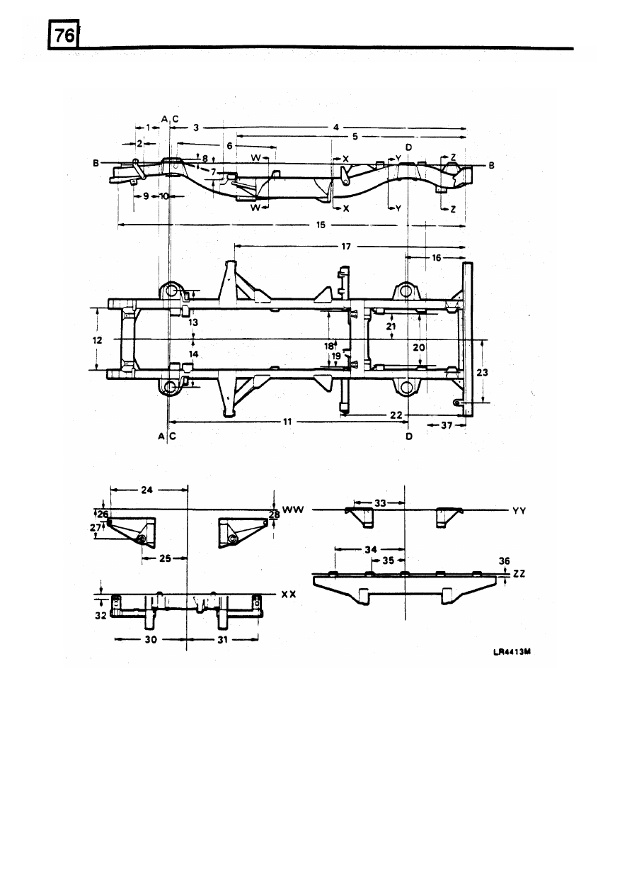
CHASSIS AND BODY
DEFENDER 90
4
REVISED: OCT
1993