Defender (1993+). Manual - part 76


  Index      Land Rover     Defender - service manual 1993 year


Search            


Content   ..  74  75  76  77   ..


Defender (1993+). Manual - part 76


STEERING 

16. 

Fit 

the drop arm, aligning the assembly marks. 

17. 

Fit  the  tab  washer  and  drop  arm  nut  and 

tighten  to  the  correct  torque  using  a  suitable 
restraining bar  between the  chassis  and  drop 
arm. 

18. 

Bend the  tab 

of 

the washer over  a convenient 

flat. 

19. 

Fit 

the  ball pin 

to 

the  drag link, tighten the nut 

and secure with a new split pin. 
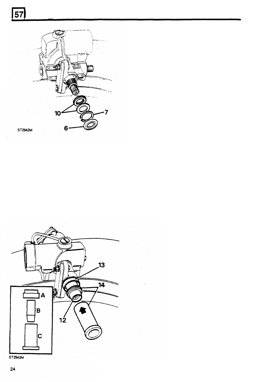
Fitting 

new  seals 

11. 

Clean the seal  housing and around the  sector 
shaft. 

12. 

Lubricate,  and  place the  seal  saver part  'B'  of 

the tool over the shaft. 

13. 

Lubricate and  fit 

part  'A' 

of 

the 

tool 

with  the 

shoulder against the face of  the 

box. 

14. 

Lubricate and  slide  the  seal,  lip  side  leading, 

over  the  seal  saver  and  with  part 

'C' 

of  the 

tool, 

drive the seal into position. 

15. 

Fit  the  anti  extrusion  washer,  dirt  seal,  and 

secure  with  the circlip. Finally fit  the dust  seal 

so 

the  the  lip  is  flat  against  the  face 

of 

the 

box. 

REISSUED: FEB 1993 

STEERING 

POWER 

ASSISTED 

STEERING 

PUMP 

OVERHAUL 

1. 

Disconnect  the  battery and  remove the  pump 

from the vehicle. 

2. 

Clean  the  exterior 

of 

the  pump  and  remove 

the drive pulley. 

3. 

Remove,  from  the  outlet  port,  the  union  nut, 

two ' O '  rings, spring and valve. 

4. 

Secure the  pump cover  removal tool 

LST 

142 

in a vice  and insert the pump in the tool. 

5. 

Fit the three 6 mm  bolts through the tool  into 

the  pump  hub.  Tighten  the  bolts  evenly  until 
the  cover 

is 

released 

from 

the  sealing  ring 

and can be removed from the  pump. 

8. 

Remove  the  pump  outer  member  and  the 
rollers. 

9.  Release  the  spring  ring 

from 

the  groove 

behind the  vane  and  push 

it 

back  towards  the 

drive shaft  housing. 

6. 

Remove  the  large  ' O '  ring  and  secure  the 

pump in a vice. 

7. 

Remove  the 

swarf 

collection  magnet  and  the 

four bolts and lift 

off 

the valve housing. 

REISSUED: 

FEB 1993 

25 

STEERING 

17.  Wrap  a smooth surface tape  round the  end of 

the drive shaft 

to 

protect the seal lip. 

18.  Lubricate the  seal  lip with power  steering fluid 

and insert the drive shaft. 

19.  Fit  the  inner  spring  ring  to  the  shaft  but 

not 

into the groove at this stage. 

20.  Fit  the  drive  key  and  the  vane  with  the  arrow 

towards  the  drive  shaft  housing  and  with  the 

raised leading edge of 

the 

vanes 

facing left. 

10.  Move the  vane back to reveal ana  remove me 

spring ring 

from 

the front 

of 

the vane. 

11.  Remove  the  vane  and  drive  key  and  rear 

spring ring. 

12.  Withdraw  the drive shaft. 
13. 

Prise-out  the 

oil 

seal  and  i f   necessary 

press-out  the  bush 

from 

the 

drive  shaft 

housing. 

14.  Clean and examine all parts for  wear. 

Assemble 

15. 

If 

removed,  press-in  a  new  bush  in the  drive 

21.  Fit  the  outer  spring  ring  to  the  groove  then 

slide the inner spring ring into the rear  groove. 

shaft  housing  to 

mm  below  the  machined 

face. 

16.  Using  the  seal  replacer  part  of  tool  number 

LST 

142, drive-in a new  seal, lip side leading, 

into the drive shaft housing. 

26 

REISSUED: 

FEB 

1993 

STEERING 

22. 

Fit 

the two  dowels to the drive shaft  housing. 

23. 

Insert the twelve rollers in the vane  and fit  the 

It 

is 

important  that  the  following  procedure  is 

pump  outer  member  with  the  milled  cut 

observed when  fitting  a  new 

or 

overhauled pump  to 

towards the drive shaft housing. 

Power assisted  steering  pump connections 

the 

vehicle 

1. 

Remove dust 

caps. 

2.  Fit clip 

to 

large feed hose. 

3. 

Push hose fully 

on 

to 

pump connection. 

4. 

Hold  clip  in position and tighten  clip  screw  to 
3 Nm. 

5. 

Screw  high  pressure  union  into  pump,  finger 
tight. 

6.  Hold pipe in correct position and tighten union 

to 20 

Nm. 

7.  Check  that  the  hose  clip  screws  securing 

hoses to fluid reservoir are tightened to  3  Nm. 

24.  Fit the  valve housing and  secure with the four 

bolts. 

Check that the pump revolves freely. 

25.  Insert the magnet into the slot provided. 

26. 

Lubricate  and  fit  the  large  ' O '  ring  and  fit the 

cover  ensuring  that  the  hole  for  the  valve 

is 

aligned  with  the  outlet  port  in  the  valve 
housing  before  the  cover  is  finally  pushed 
home over  the seal. 

27. 

Lubricate and  fit  the  valve,  spring,  large  and 
small ' O '  rings and the union nut. 

28. 

Finally, fit  the drive pulley with 

the 

three 

bolts 

and washers. 

29.  Fit dust caps 

to 

inlet and outlet connections. 

REISSUED: 

FEB 1993 

27 


Content   ..  74  75  76  77   ..