Defender (1993+). Manual - part 67
FRONT AXLE AND FINAL DRIVE
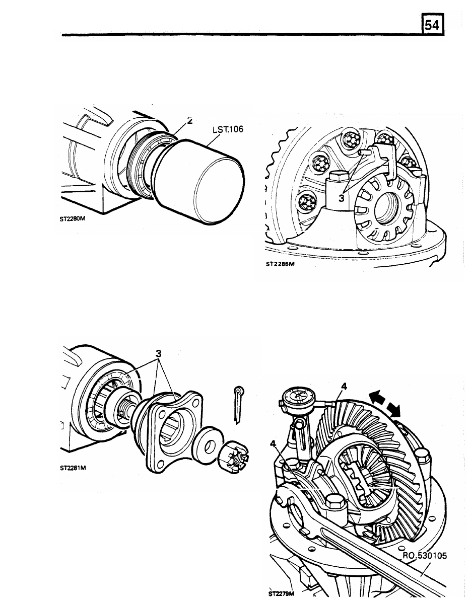
position.
tighten the nut with just sufficient nip to
2.
Smear the outer diameter of the new seal with
remove any backlash between the crown
a recommended all purpose grease and with
the lip side leading, start it squarely into the
3. Line up the centre of the locking finger lug
pinion nose .housing. Using special service
with a slot in the adjusting nut. Fit the locking
tool L.S.T. 106, drive the seal home to the
finger and secure with the roll pin. Fit the
depth determined by the tool.
opposite nut and tighten, with the above
wrench, until resistance is felt.
3. Lubricate the seal lips with a recommended
axle oil. Check that the flange seal running
surface
is
clean, smooth and free
from
imperfections that could damage the seal.
Carefully fit the drive flange and secure with
the washer and nut. Tighten the nut to the
4.
Mount the pinion height setting gauge, with
correct torque whilst holding the flange with
the magnetic base on the pinion housing
restraining tool 18G 1205.
If
necessary
flange and the stylus resting against a crown
continue to tighten
the
nut to line up the split
wheel tooth. Continue
to
tighten the nut, on
pin hole and fit a new split pin.
the carrier side, until a backlash of 0,10 to
0,17 mm is achieved.
Do
not slacken the
crown wheel side
nut
otherwise the backlash
and bearing pre-load will be lost. Line
up
the
locking finger lug with a slot
in
the nut.
Adjust crown wheel and pinion backlash
1.
Return the pinion housing to the vertical
position and lower the crown wheel and
differential assembly into the pinion housing.
Lubricate the carrier bearings and fit the
tracks. Fit the bearing caps
so
that the
assembly marks line up and fit the bolts,
finger tight only.
2.
Move the crown
wheel
into mesh with the
pinion and
fit
the bearing adjusting nut on the
crown wheel side Using wrench RO 530105
wheel and pinion.