Defender (1993+). Manual - part 39


  Index      Land Rover     Defender - service manual 1993 year


Search            


Content   ..  37  38  39  40   ..


Defender (1993+). Manual - part 39


CLUTCH 

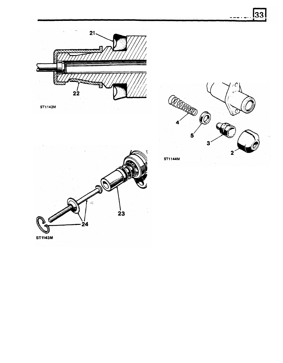
OVERHAUL SLAVE CYLlNDER 

Dismantle 

Remove the slave cylinder 

from 

the  vehicle. 

3. 

Expel  the  piston  assembly,  applying  low 

4. 

Withdraw 

the 

spring. 

2. 

Withdraw the dust cover. 

pressure air to  the fluid inlet. 

5.  Prise 

off  the seal from the piston. 

23. 

Smear  the  piston  with  rubber  grease  and 

insert  the  assembly,  valve  end  first,  into  the 
cylinder. 

24. 

Fit the push-rod, retaining washer and circlip. 

Inspection 

6. 

Clean  all  components with  cleaning  fluid  and 
allow 

to 

dry. 

7. 

Examine the  cylinder  bore and  piston, ensure 

that  they  are  smooth  to  the  touch  with  no 
corrosion,  score  marks  or  ridges. 

If 

there 

is 

any doubt, fit  new replacement. 

8. 

The  seal  should  be  replaced  with  a  new 

component. 

Assemble 

9. 

Smear  the  seal  with  rubber  grease  and  the 
remaining internal items with  brake and  clutch 
fluid. 

10. 

Fit the seal, large diameter  last, 

to 

the piston. 

11. 

Locate the  conical  spring,  small diameter  first, 

over the front end of  the piston. 

12. 

Smear  the  piston  with  rubber  grease  and 

insert  the  assembly,  spring  end  first,  into  the 
cylinder. 

13. 

Fill the  dust  cover  with  rubber  grease  and 

fit 

the cover 

to 

the cylinder. 

CLUTCH 

CLUTCH  PEDAL  AND 

MASTER  CYLINDER 

BLEED CLUTCH HYDRAULIC SYSTEM 

ADJUSTMENT 

When  the  gearbox  and  bell  housing  assembly  has 
been fitted 

to 

the vehicle the  hydraulic clutch release 

system must be bled 

to 

expel air, 

NOTE:  During the  following  procedure, keep the 

fluid  reservoir topped-up  to  avoid  introducing air 

Adjust 

into the system. Use only the fluid  recommended 
in the  Lubrication chart.  Use only  new fluid  from 

2. 

Withdraw  the  six  screws  and  remove the  top 

a sealed container. 

plate. 

3. 

Slacken  master  cylinder  push-rod  locknuts to 

1. 

Attach  a  length of  suitable tubing 

to 

the  slave 

provide  free  movement 

of 

the  push-rod 

cylinder  bleed  screw  and  immerse 

the 

free 

through the pedal trunnion. 

end  of  the  tube  in a  glass  jar  containing  new 

4. 

Slacken the adjustment screw  locknut. 

clutch fluid. 

5. 

To  increase  the  pedal  height,  turn  the 

2.  Slacken  the  bleed  screw  and  depress  the 

adjustment  screw  anti-clockwise.  To  reduce 

clutch  pedal,  pausing  at  the  end 

of  each 

turn clockwise. 

stroke,  until the fluid issuing from the tubing is 

When correct tighten the locknut. 

free  of  air  with  the  tube  free  end  below the 

6. 

To  adjust  the  master  cylinder  push-rod, check 

surface 

of 

the  fluid  in  the  container.  Whilst 

that  the  push-rod  has  free-play  through  the 

holding  the  clutch  pedal  down  and  with  the 

trunnion. 

free  end  of  the  tube  below  the  fluid,  tighten 

7. 

Adjust 

the 

locknuts 

until the  push-rod has 

1,5 

the bleed screw. 

mm  free-play  between  the  push-rod  and 
master  cylinder.  When  correct  tighten  the 
locknuts. 

8. 

Check  that  there 

is 

mm  free  movement  of 

the  pedal  at  the  pad. 

If 

necessary  re-adjust 

the push-rod. 

9.  Refit the top plate. 

1. 

The  correct  height  for  the  clutch  pedal  from 
the  floor  of the  footwell,  without  a mat, 

to 

the 

lower edge of  the pedal is 

140 

mm, dimension 

A'. 

CLUTCH 

RENEW CLUTCH SLAVE  CYLINDER 

RENEW  CLUTCH MASTER CYLINDER 
Left hand drive vehicles 

To  Remove 

1. 

Evacuate clutch system  fluid  at  slave  cylinder 

2.  Remove the bonnet. 

2.  Disconnect fluid pipe. 

cylinder 

to 

the the servo. 

3.  Remove 

two 

securing  bolts  and  withdraw 

4. 

Carefully  ease  the  master  cylinder  away  from 
the  servo  without  imposing  any  strain  upon 
the brake fluid pipes. 

4. 

If 

dust  cover  is  not  withdrawn  with  slave 

5.  Disconnect  the  vacuum  hose  from  the  servo 

and move aside. 

6. 

Disconnect 

the  two 

brake lamp lucars. 

7. 

From  inside  the  vehicle,  remove  the  fibre 
board closing panel above the pedals. 

8. 

Release the two return springs from  the  brake 
pedal and single spring from the clutch pedal. 

9. 

Remove the six  bolts securing the brake pedal 
box  to  the  bulkhead  and  carefully  withdraw 

the  pedal  box  with  the  servo  sufficiently  to 

allow  clearance  for  the  clutch  master  cylinder 
and pedal box 

to 

be withdrawn. 

10. 

Remove  the 

SIX 

bolts  securing  the  clutch 

pedal box 

to 

the bulkhead. 

bleed valve. 

3. 

Remove  the 

two 

nuts  securing  the  master 

slave cylinder and backing plate. 

cylinder, withdraw it from bell housing. 

To Refit 

5. 

Withdraw  dust  cover  and  backing  plate  from 
slave cylinder. 

6.  Coat both sides  of  backing plate with  Hylomar 

P232M waterproof jointing compound. 

7. 

Locate  backing  plate  and  dust  cover  in 

position on slave cylinder. 

8. 

Fit  slave  cylinder, engaging  push rod through 

centre  of  dust  cover  and  with  bleed  screw 
uppermost. 

9. 

Reconnect fluid pipe. 

11. 

Release  the  hydraulic  pipe  from  the  dutch 
master cylinder and cover the end. 

12.  Remove the clutch  pedal and  master cylinder 

assembly from the vehicle. 

13.  Remove  the  reservoir  cap  and  discard  the 

fluid. 

14.  Remove the six screws and lift-off  the  pedal 

box top cover and gasket. 

15.  Remove the two  nuts and bolts  that  secure. 

the master cylinder to the pedal box: 

16.  Remove  the  nut  and  washer  from  the  end  of 

the master cylinder push rod. 

17.  Withdraw  the  master  cylinder  and  steel 

gasket. 

18.  Fit  the  two  locknuts  and  plain  washer  to  the 

10.  Replenish and bleed clutch system. 
11.  Check  for  fluid  leaks  with  pedal  depressed 

push-rod. 

and also with system at rest. 

1.  Disconnect  the  battery. 

CLUTCH 

Refitting 

19. 

Fit 

the  master cylinder and  steel gasket 

to 

the 

pedal box  and  insert the  push-rod through the 
bush  and  trunnion  and  loosely  fit 

the 

single 

nut 

to 

the end of  the push-rod. 

20. 

Secure  the  master  cylinder  with  the  two  nuts 

and bolts to the pedal box. 

21.  Fit  the  pedal  box  to  the  bulkhead  resealing 

with  Bostic  adhesive  and  secure  with  the  six 
bolts. 

22.  Check  the  clutch  pedal  height  and free-play, 

adjust  if  necessary.  Tighten the push-rod  end 
nut. Connect the return spring to the pedal. 

23.  Fit the pedal box  top cover with a new gasket 

and secure with the six screws. 

24.  Connect the fluid pipe to the  master cylinder. 
25.  Fit  the  brake  servo  and  pedal  box  assembly, 

reseal  with  Bostic  adhesive  and  secure  with 
the six bolts. 

26. 

Connect the return springs to the pedal. 

27. 

Fit the brake master cylinder to the servo and 

tighten the two nuts, 

28.  Fit the fibre board closing panel. 
29.  Connect the stop lamp lucars. 
30.  Attach the three way pipe union bracket to the 

servo ('90' models). 

31.  Connect the vacuum hose to the servo. 
32.  Fill  the  clutch  master  cylinder  with  new  fluid 

from 

sealed 

container 

of 

the 

recommmended  grade  to  the  level  mark  on 
the side of the reservoir. 

33.  Bleed  the clutch  hydraulic  system  and  fit  the 

reservoir cap. 

34.  Connect  the  battery,  fit  the  bonnet  and  road 

test the vehicle. 


Content   ..  37  38  39  40   ..