Defender (1993+). Manual - part 27
 

  Index      Land Rover     Defender - service manual 1993 year


Search            


Content   ..  25  26  27  28   ..


Defender (1993+). Manual - part 27


ENGINE 

TIMING CHAIN AND  CHAINWHEELS 

Remove 

1.  Remove engine. 

2. 

Remove flywheel. 

1.  Remove front cover. 

3.  Remove dipstick. 

2. 

Remove  retaining  bolt  and  washer,  remove 

4. 

With  assistance,  invert  engine,  support 

on 

distributor  drive gear and spacer. 

3. 

Ensure number one piston is at  TDC. 

4.  Remove  chainwheels  and  chain  as  an 

6. 

Remove rear  main bearing cap. 

assembly. 

7. 

Remove cross seals from cap. 

8. 

Remove crankshaft rear oil seal. 

9. 

Clean  main  bearing  cap  and  oil  seal  area 

of 

CRANKSHAFT REAR  OIL  SEAL 

blocks. 

5. 

Remove sump. 

Refit 

5. 

Clean chainwheels and chain. 

6. 

Fit  chainwheels  to  chain,  aligning  timing 

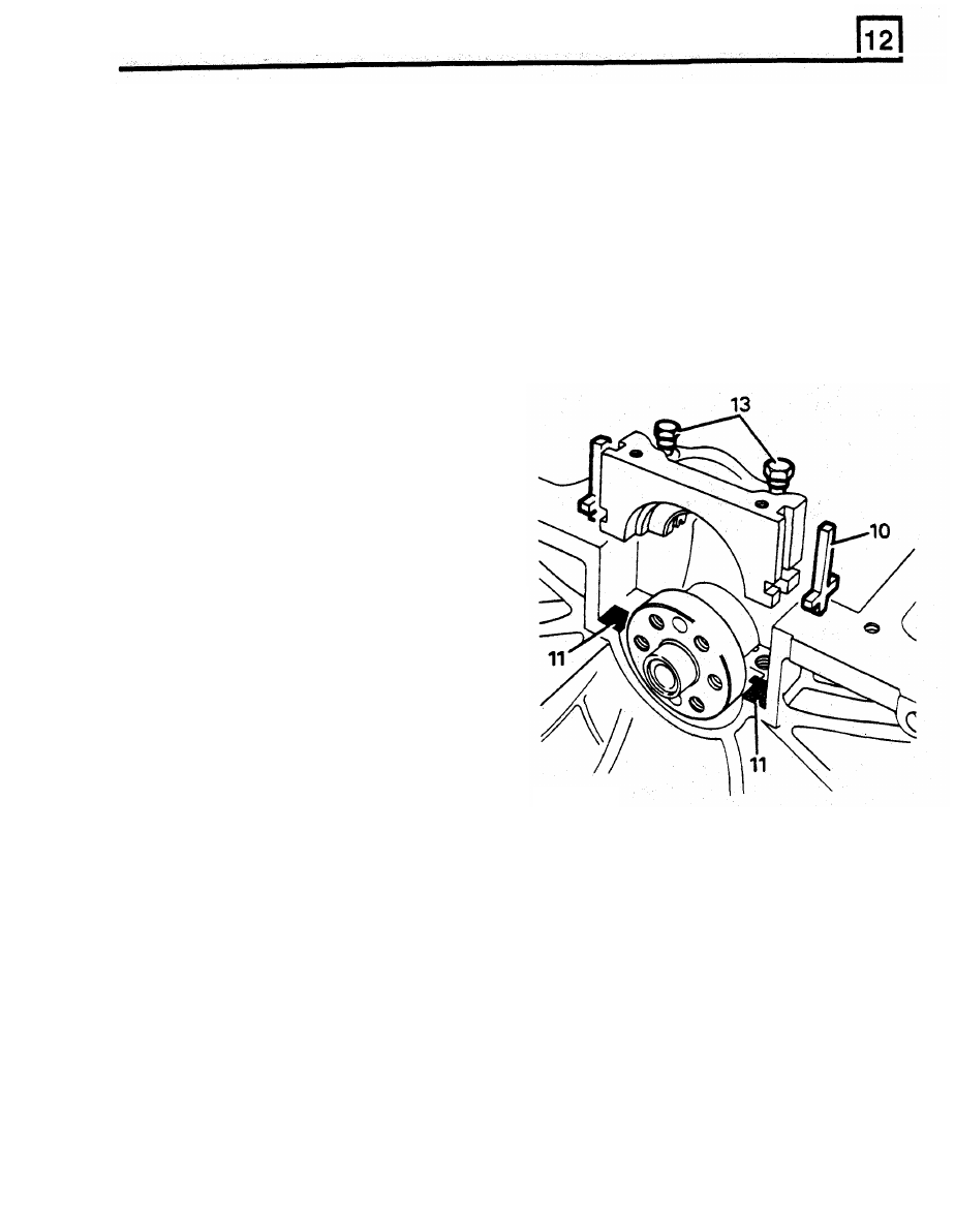
11. 

Apply Hylomar SQ32M to block as illustrated. 

marks. 

7. 

Ensure camshaft  key  is  fitted parallel to  shaft 

axis 

to 

ensure  adequate  lubrication  to 

distributor drive gear. 

8. 

Engage  chainwheel  assembly  on  camshaft 

and crankshaft keys, ensure chain wheels  are 
fully  located. 

9. 

Check  alignment  of  timing  marks with  straight 
edge. 

10. 

Fit spacer  with flange to front, 

11.  Fit  distributor  drive  gear  with  groove  towards 

spacer. 

12.  Fit  retaining  bolt  and  washer,  tighten 

to 

58 

Nm. 

13. 

Fit front cover. 

10.  Fit new 

cross seals 

to bearing cap. 

FLYWHEEL 

Remove 

1.  Remove gearbox  and clutch. 

2. 

Slacken starter  motor bolts. 

3. 

Lock  flywheel,  remove  flywheel  bolts  and 

RR3827M 

flywheel. 

12. 

Lubricate bearing shell  and  cross  seals  using 

13. 

Fit bearing cap, do not tighten bolts. 

on the  block. 

Refit 

clean engine oil. 

4.  Clean components for  reassembly. 

14.  Ensure cap  is fully  home and  seated  squarely 

5.  Fit flywheel. 

6. 

Lock  flywheel,  fit  flywheel  bolts,  tighten to 

80 

Nm. 

block. 

RR3828M 

ENGINE 

15. 

Ensure 

oil 

seal  guide  RO1014  and  crank 

journal  are  scrupulously  clean.  Coat  seal 
guide  and  oil  seal  journal  with  clean  engine 
oil. 

CAUTION: 

Do 

not handle oil seal lip, check 

it 

is 

not damaged. Ensure outside diameter 

remains clean and dry. 

16.  Position oil  seal guide RO1014 on crankshaft 

flange. 

NOTE:  lubricant  coating  must  cover  seal 

guide  outer  surface  completely  to  ensure 
that  oil  seal 

lip 

is 

not  turned  back  during 

assembly.  Position 

oil 

seal, 

lipped  side 

towards  engine,  on  seal  guide.  Seal 
outside diameter 

MUST be 

clean and dry. 

17.  Push oil  seal  fully  and  squarely  by  hand  into 

recess 

in  cap  and  block  until  it  contacts 

machined step in recess. Remove seal guide. 

18. 

Tighten rear main bearing cap to 90 Nm. 

19.  Fit sump. 

20. 

Reposition engine, 

fit 

dipstick. 

21 

Fit flywheel. 

22. 

Fit engine to vehicle. 

RO605351 

18G1150 

18G1150E 

18G79 

ENGINE 

LRT-12-041 

Guide bolts 

RO605351 

LRT-12-013 
18G1150 

Piston pin remover/replacer 

Basic 

tool 

LRT-12-014 
18G1150E 

Adaptor remover/replacer 

piston pin 

LRT-12-001 

Clutch  centralising 

tool. 

18G79 

ENGINE 

MS1519A 

RO.600959 

LRT-12-034 

Spring compressor 

MS1519A 

LRT-12-038 
RO600959 

exhaust


Drift 

Valve guide replacement 

intake and 

LRT-12-515 
RO605774A 

Distance piece 

for 

valve guide 

LRT-12-504 

Valve seat cutter 

MS621 

MS.621 


Content   ..  25  26  27  28   ..