Defender Electric Diagrams. Manual - part 258
ABBREVIATIONS
DEFENDER (LHD) - VIN: 751063 > -
2
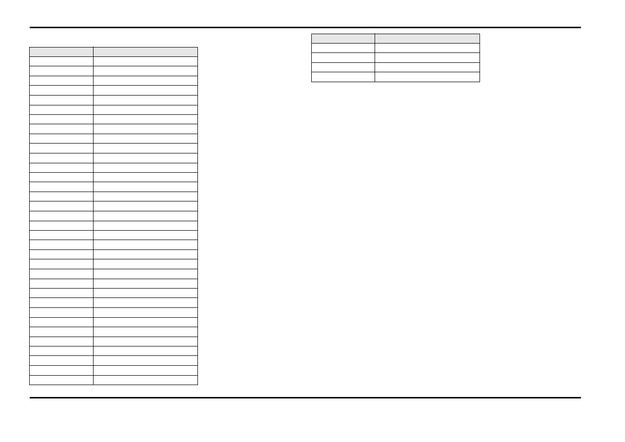
ABBREVIATIONS
Abbreviation
Description
ABS
Anti-lock braking system
ADRC
Adaptive damping
AFS
Adaptive front lighting system
AUTO
Automatic transmission
CAN
Controller area network
DAB
Digital audio broadcasting
DSC
Dynamic stability control
D4
Diesel engine - Straight-four
DV6
Diesel engine - V6
DV8
Diesel engine - V8
EGR
Exhaust gas recirculation
FBH
Fuel burning heater
FET
Field effect transistor
GPS
Global positioning system
HS CAN
High speed controller area network bus
IC
Instrument cluster
IP
Instrument panel
PV6
Petrol engine - V6
PV8
Petrol engine - V8
PV8NA
Naturally aspirated engine - V8
PV8SC
Super charged engine - V8
LH
Left-hand
LIN
Local interconnect network
MAF/IAT
Mass air flow / intake air temperature
IBOC
In band on channel
MS CAN
Medium speed controller area network bus
NAS
North American specification
PDC
Park distance control
RH
Right-hand
SAI
Secondary air injection
SCL
Steering column locking
SDARS
Satellite digital audio receiver system
TCM
Traction control module
TPMS
Tire pressure monitoring system
TSD
Touch screen display
ULEV
Ultra low emission vehicle
USB
Universal serial bus
VICS
Vehicle information control system
Abbreviation
Description