Defender Electric Diagrams. Manual - part 102


  Index      Land Rover     Land Rover Defender Electric Diagrams - manual 1997 year


Search            


Content   ..  100  101  102  103   ..


Defender Electric Diagrams. Manual - part 102


INTRODUCTION

1.8

DEFENDER 1999 MY

Colour - If applicable, the colour of the connector housing is shown.
NATURAL is used to describe connectors with a clear/translucent plastic
finish.

Location statement - Used in conjunction with the photograph to
determine the location of the connector.

Photograph - Shows the location of the subject connector. In most cases,
the photograph will indicate the amount of trim removal necessary to reveal
the connector. For convenience some photographs identify more than one
connector.

Derivatives - Unless specified otherwise, location statements and
photographs relate to all models.

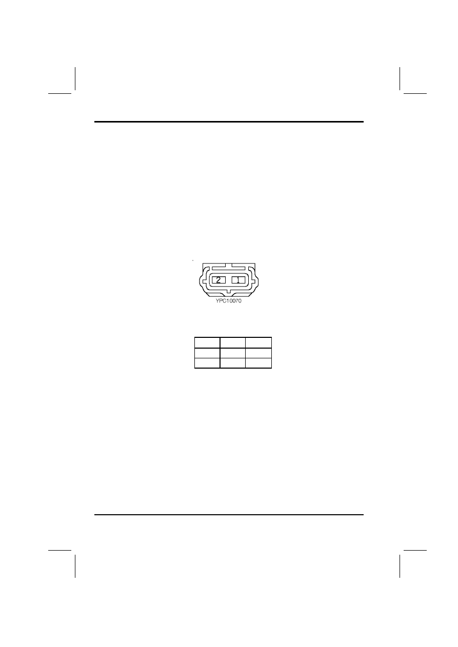
Face view - An outline of the connector housing, viewed from the front,
showing pin numbers (if applicable).

Pin-out table - A three column table, detailing the colour and position of
each wire in the connector:

Cav

Col

CCT

1

GR

ALL

2

B

ALL

1. Cav:The connector pin (cavity) number.
2. Col:The colour of wire populating the connector pin.
3. Cct:Identifies the model or feature which uses the wire. ALL means

applicable to all vehicles in the range.

INTRODUCTION

DEFENDER 1999 MY

1.9

The 1999 MY Defender model range features a number of different derivatives.
To identify which vehicle a specifuc feature applies to, the following CCT’s are
used in the connector section of this Electrical Reference Library.

Cct

Model or feature

1

Air Conditioning

2

No Air Conditioning

3

RHD

4

LHD

7

90"

8

110"

9

130"

10

ABS - RHD

11

ABS - LHD

12

ABS

13

Non ABS - RHD

14

Non ABS - LHD

15

Anti-theft Alarm

16

Anti-theft Alarm - LHD

17

Anti-theft Alarm - RHD

18

No Anti-theft Alarm - LHD

19

No Anti-theft Alarm - RHD

21

Td5 Engine

22

Non Td5 Engine

23

M52 Engine

24

TDi Engine

25

Dim Dip

26

No Dim Dip

27

Headlamp Levelling

28

Petrol Engine

29

110 Station Wagon

30

90 Station Wagon

31

90/110 Hard Top

32

90/110 Station Wagon

INTRODUCTION

1.10

DEFENDER 1999 MY

WIRE COLOUR CODES

The following list contains the wire colour codes used on the vehicle harnesses
and is intended to give an indication of the function or feature for which a
particular colour of wire is normally used. These guidelines do not always apply
to the wiring between components and the main harness.

Code

Colour

Function

B

Black

Earth wire from a component to an earth tag.

G

Green

Ignition fused supply from passenger compartment

fuse box: clock, instrument, indicators, electric mirrors.

K

Pink

Fused supply: central door locking.

LG

Light

Green

Ignition auxiliary fused supply from passenger

compartment fuse box: reverse lamps, brake lamps.

N

Brown

Battery supply to ignition switch from fusible links 3

and 5.

O

Orange

Fused supply: central locking.

P

Purple

Fused permanent supply: interior lamps, radio

cassette, clock, anti-theft alarm, electric aerial.

R

Red

Fused supply: side lamps.

S

Slate

(grey)

Fused supply: electric windows.

U

Blue

Fused supply: headlamps, cooling fans.

W

White

Ignition switched supply to passenger compartment

fuse box.

Y

Yellow

Ignition switched supply to passenger compartment

fuse box.

INTRODUCTION

DEFENDER 1999 MY

1.11

Fault diagnosis
When diagnosing an electrical fault follow the steps below:

1. Read the circuit description and study the circuit diagram appropriate to

the reported fault to ensure a good understanding of circuit operation.

2. Study the power distribution, fuse details and earth distribution diagrams

and identify other circuits which share fuses and/or earth points. Check
whether these circuits operate correctly.

3. Using the photographs contained in the Connector section, locate a point

on the circuit (approximately half way between supply and earth) which is
easily accessible.

4. Check that the pin out details of the connector are correct and that the

correct signals exist at the correct terminals.

5. Using the marker pen supplied (or other suitable non-permanent marker

pen), mark the parts of the circuit you have verified.

6. Continue to the next point on the circuit which is easiest to access and

repeat the above.

7. Continue this approach until a fault is found, rectify the fault and then

verify that the circuit operates correctly.


Content   ..  100  101  102  103   ..