Defender Electric Diagrams. Manual - part 10
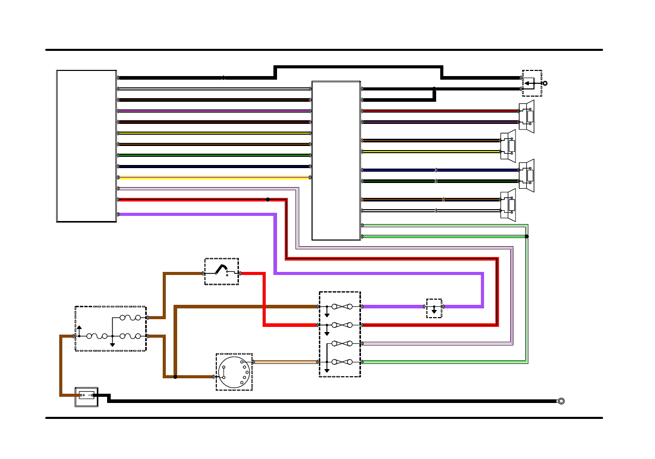
DEFENDER 90-NAS
97 MODEL YEAR
IN2
IN1
2A
2B
1
POS4-CRANK
POS3-IGN
POS2-AUX
GROUND
MAIN
60 AMP
LINK 5
100 AMP
LINK 1
13.5 VOLTS
15 AMP
7.5 AMP
FUSE 6
FUSE 5
FUSE 2
5 AMP
FUSE 11
10 AMP
3
1
2
IGNITION (S176)
JOINT (K108)
EARTH HEADER
C41-1
C573-2
C570-2
C289-11
C289-9
C491-2
C491-1
C580-3
C99-1
C581-1
C580-7
C491-3
C28-1
C632-1
C580-12
C580-10
C580-4
C581-2
C339-2
C92-8
C92-7
C92-6
C92-5
C92-4
C92-3
C92-2
C92-1
C491-6
C491-13
C491-11
C491-7
C491-14
C492-1
C492-2
C492-3
C492-4
C492-5
C492-6
C492-7
C492-8
C550-6
C98-2
C98-8
C98-4
C340-2
C340-1
C308-1
C309-1
C339-1
C391-1
C310-1
C491-4
C491-12
C491-5
C379-4 C393-4
C379-2 C393-2
C379-3 C393-3
C379-1 C393-1
C491-8
C491-9
C550-3
C98-7
C98-6
A376
A87
A174
A122
A81
SJ1
A85
A84
LIGHTING SWITCH (S100)
BATTERY (P100)
SPEAKER-RH (F118)
REAR DOOR
SPEAKER-LH (F119)
REAR DOOR
HEADER JOINT (K109)
FUSEBOX (P108)
COMPARTMENT
ENGINE
PASSENGER COMPARTMENT FUSEBOX (P101)
RADIO/CASSETTE PLAYER (F100)
RADIO/CASSETTE POWER AMPLIFIER (F111)
B,1.5
B,1.5
WLG,1.0
B,1.0
N,4.5
BR,0.5
BN,0.5
BW,0.5
BU,0.5
BO,0.5
BY,0.5
B,1.0
BU,1.0
BG,1.0
BW,1.0
BO,1.0
BK,1.0
BG,1.0
BN,1.0
BR,1.0
BY,1.0
BN,1.0
BU,1.0
BW,1.0
B,1.5
N,10.0
N,3.0
B,15.0
YP,0.5
WO,2.0
N,2.0
N,3.0
P,1.5
RB,1.0
WLG,1.0
BK,0.5
RB,0.5
WK,0.5H
R,1.5
P,1.0
WLG,1.0
BG,0.5
WK,0.5H
IN-CAR ENTERTAINMENT
50.1
LINK 3
60 AMP
C41-2
FRONT-LH (F108)
DOOR SPEAKER-
DOOR SPEAKER-
FRONT-RH (F107)