Defender. Manual - part 291


  Index      Land Rover     Land Rover Defender - service manual 2007 year


Search            


Content   ..  289  290  291  292   ..


Defender. Manual - part 291


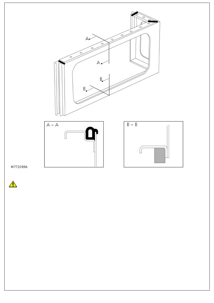
Section A-A shows a rubber seal in position on the body side rear upper assembly.

CAUTION: Ensure rubber seal is correctly seated into channel.

Section B-B shows a foam seal located on the bottom edge of the body side rear upper assembly. It is fixed to the panel

using double sided tape.

Body side lower

CAUTION: Ensure seals are fitted before refitting assembly.

The arrows indicate the position of two foam seals.

Body Repairs - Water Leaks - Water Leaks

Description and Operation

WATER LEAKS

Sealing charts in the Corrosion Protection section show those areas of the bodyshell most likely to be affected by

accident damage and water leaks, and which could therefore require re-treatment in repair. They do not show those

joint areas which only apply to factory assembly operations and which are unlikely to be disturbed in service (e.g. centre

tunnel), or where the damage would be so severe that the entire bodyshell would normally be written off.

When water leakage occurs, always adopt a logical approach to the problem using a combination of skill, experience and

intuition. Do not attempt to reach a conclusion based only on visual evidence, such as assuming that a leak emanates

from the windscreen because the footwell is wet. It will often be found that the source of the leak is elsewhere. The

correct procedure will increase the chance of locating a leak, however obscure it may seem.

Tools and Equipment

The following tools and equipment are recommended for detection and rectification of water leaks:

Garden sprayer (hand-operated).

Wet/dry vacuum cleaner.

Dry absorbent cloths.

Battery torch.

Small mirror.

Weatherstrip locating tool.

Trim panel remover.

Small wooden or plastic wedges.

Dry compressed air supply.

Hot air blower.

Sealer applicators.

Ultrasonic leak detector.

During leak detection, the vehicle should be considered in three basic sections:

The front interior space;

The rear passenger space, where applicable;

The rear loadspace or boot.

Testing

From the information supplied by the customer it should be possible for the bodyshop operator to locate the starting

point from which the leak may be detected. After the area of the leak has been identified, find the actual point of entry

into the vehicle. A simple and effective means initially is an ordinary garden spray with provision for pressure and jet

adjustment. This will allow water to be directed in a jet or turned into a fine spray. Use a mirror and a battery-powered

torch (NOT a mains voltage inspection lamp) to see into dark corners.

The sequence of testing is particularly important. Start at the lowest point and work slowly upwards, to avoid testing in

one area while masking the leak in another. For example, if testing started at the level of the windscreen, any water

cascading into the plenum chamber could leak through a bulkhead grommet and into the footwells. Even at this point it

could still be wrongly assumed that the windscreen seal was at fault.

Another important part of identifying a water leak is by visual examination of door aperture seals, grommets and

weatherstrips for damage, deterioration or misalignment, together with the fit of the door itself against the seals.

Sealing

When the point of the leak has been detected, proceed to rectify it using the following procedure:

Renew all door aperture seals and weatherstrips which have suffered damage, misalignment or deterioration.

Check all body seals to ensure that they are correctly located on their mounting flanges/faces using a locating

tool if necessary.

Dry out body seams to be treated using compressed air and/or a hot air blower as necessary.

Apply sealant on the outside of the joint wherever possible to ensure the exclusion of water.

When rectifying leaks between a screen glass and its weatherstrip (or in the case of direct glazing, between the

glass and bodywork), avoid removing the glass if possible. Apply the approved material either at the glass to

weatherstrip or glass to body.

Body Repairs - Vehicle Specific Information and Tolerance Checks - Body

and Frame

Description and Operation

CHASSIS AND BODY

Chassis

The chassis on all Defender variants are of the box section, ladder type construction, manufactured from 2 mm (14swg)

steel and treated with zinc phosphate, cathodic electro coated, followed by waxing in the rear cross member.

Outriggers and angled brackets welded to the chassis support suspension and axle components and are also used as

body mounting points. A detachable box section cross member, located between the two chassis longitudinals is fitted to

facilitate main gearbox and transfer box assembly removal.

Should chassis damage occur, a comprehensive range of components are available, including body support outriggers,

cross members and radius arm mounting brackets. ALWAYS fit genuine parts that are fully guaranteed and to original

equipment specification, fitted with Land Rover's BS 5135 welding standard.

Body

All body panels, with the exception of the fascia bulkhead, are manufactured from aluminium alloy. Galvanized steel is

used for the front wheel arches to give optimum protection. Most panels are also treated with zinc phosphate and

cathodic electro coated with polyester surfacer, and are bolted to the welded chassis.

CHASSIS FRAME ALIGNMENT

With the vehicle assembled, a check for chassis squareness can be made as follows:

1. Place the vehicle on a level floor.

2. Mark measuring points at approximately the locations shown in LR4412M ensuring that the marks are exactly

opposite on each side of the chassis frame.

3. Hold a plumb line against each of the measuring points in turn and mark the floor directly beneath the plumb-

bob.

4.Move the vehicle and measure diagonally between the marks made on the floor, if the chassis is square the

diagonals between the related measuring points should agree within 9,50 mm.

5.Chassis frame dimensional checks can be made, with the vehicle upper structure removed, referring to the

applicable illustration and associated key.


Content   ..  289  290  291  292   ..