Defender. Manual - part 252


  Index      Land Rover     Land Rover Defender - service manual 2007 year


Search            


Content   ..  250  251  252  253   ..


Defender. Manual - part 252


Rear View Mirrors - Interior Mirror

Removal and Installation

Removal

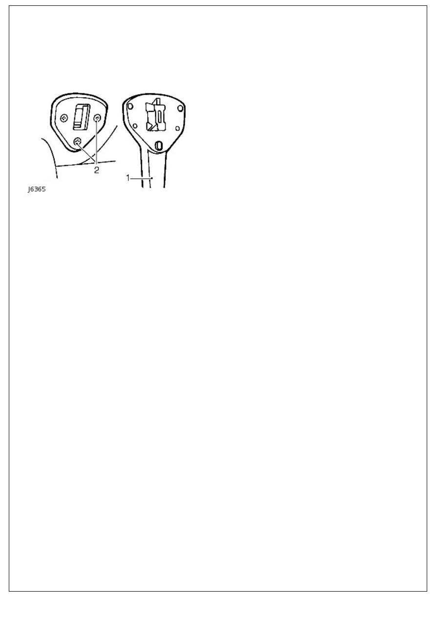
1. Prise interior mirror arm from mounting plate.

2. Remove 3 screws and remove mounting plate from

headlining.

Installation

1. Install mounting plate to headlining.
2. Locate lower lug of mirror arm in mounting plate aperture.
3. Press mirror arm firmly to engage the spring clip.

Seating -

Torque Specifications

Description

Nm

lb-ft

Rear seat base stop bolt

23

17

Rear seat bolts

23

17

Rear seat nuts

23

17

+ Front seat backrest nuts and bolts

23

17

Front seat bolts

23

17

Third row seat bolts

23

17

Third row seat nuts

23

17

Third row seat nut and bolt

23

17

+ New nuts must be installed

Seating - Seats

Description and Operation

COMPONENT LOCATION

OVERVIEW

Vehicles from 2007 model year are fitted with an all new seating system. The front seats are manually adjustable for

reach and recline. Some vehicles may also feature heated front seats. The heated front seats will only operate when the

ignition is switched on.

The second row seats feature a 60/40 split and are able to be folded forward to increase the loadspace in the rear of the

vehicle. Defender 110 Station Wagons are fitted with 2 forward facing third row seats. The third row seats can be

stowed at the side of the cabin to increase the loadspace in the rear of the vehicle. For more information on seat

stowage, refer to the Owners Handbook.

PRINCIPLES OF OPERATION

Heated Front Seats

When the ignition switch is in position II (ignition on) a feed is provided to the window lift relay coil via the central

junction box (CJB). The ground path for the relay coil is controlled by the left-hand (LH) and right-hand (RH) heated

seat switches. When either switch is pressed, the relay energizes and provides a battery voltage feed to the appropriate

seat heater elements. Both seats contain 2 heating elements; 1 in the cushion, 1 in the backrest, which are wired in

series.

The cushion elements in both front seats contain a thermostatically controlled switch. When the cushion element

temperature reaches 37 ± 3°C (98 ± 3°F) the thermostat cuts the supply to both the cushion and backrest elements.

When the temperature of the cushion element falls below 28 ± 3°C (82 ± 3°F) the thermostat reinstates the supply to

both heater elements.

Seating - Front Seat

Removal and Installation

Removal

1. Remove the front seat cushion. 

For additional information, refer to: 

Front Seat Cushion

 (501-

10 Seating, Removal and Installation).

2. Remove the front 2 bolts from the front seat.

Disconnect the front seat heater mat electrical

connector.

3. Remove the front seat.

Slide the front seat forwards.

Remove the 2 bolts.

Collect the 8 spacer washers.

Installation

1. To install, reverse the removal procedure.

Tighten the bolts to 23 Nm (17 lb.ft).


Content   ..  250  251  252  253   ..