Defender. Manual - part 241


  Index      Land Rover     Land Rover Defender - service manual 2007 year


Search            


Content   ..  239  240  241  242   ..


Defender. Manual - part 241


memory.

The anti-theft system module also controls;

the active anti-theft system. 

For additional information, refer to: 

Anti-Theft - Active

 (419-01A Anti-Theft - Active, Description and Operation).

the central locking system. 

For additional information, refer to: 

Handles, Locks, Latches and Entry Systems

 (501-14 Handles, Locks, Latches

and Entry Systems, Description and Operation).

interior lighting. 

For additional information, refer to: 

Interior Lighting

 (417-02 Interior Lighting, Description and Operation).

the hazard flashers. 

For additional information, refer to: 

Exterior Lighting

 (417-01 Exterior Lighting, Description and Operation).

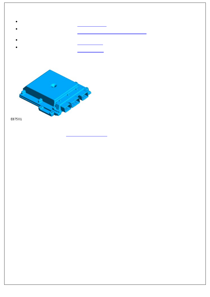
ENGINE CONTROL MODULE

The ECM is mounted on the engine compartment bulkhead and works in conjunction with the anti-theft system module

to control the passive anti-theft system. 

For additional information, refer to: 

Electronic Engine Controls

 (303-14 Electronic Engine Controls - 2.4L Duratorq-TDCi

HPCR (103kW/140PS) - Puma, Description and Operation).

CONTROL DIAGRAM

• NOTE: = Hardwired; = High speed controller area network (CAN) bus

Item

Part Number

Description

1

-

Battery

2

-

Transceiver coil

3

-

Anti-theft system module

4

-

Diagnostic socket

5

-

Instrument cluster

6

-

ECM

7

-

CJB

8

-

Starter relay

9

-

Ignition switch

10

-

BJB

11

-

Glow plug relay

PRINCIPLES OF OPERATION

The anti-theft system module receives a permanent battery supply from fuse 7 in the BJB. When the vehicle key is

placed in the ignition barrel and turned to position II (ignition on), the anti-theft system module will also receive a

power supply from fuse 8 of the CJB.

When the anti-theft system module receives the ignition switch feed it activates the transceiver coil by supplying a

battery voltage feed from pin 12 of connector C0057, and a pulsed voltage signal from pin 7 of connector C0057.

The pulsed feed from the anti-theft system module causes the magnetic field created by the transceiver coil to collapse

and restore. The fluctuating magnetic field activates the remote RF handset to transmit a mobilization code to the anti-

theft system module.

The anti-theft system module receives the mobilization code via its antenna. This code is compared to a value in its

memory. If the codes match, the anti-theft system module provides a mobilization signal to the instrument cluster. The

instrument cluster acts as a gateway, converting the signal transmitted from the anti-theft system module into a signal

that is recognizable by the ECM. This signal is then transmitted by the instrument cluster to the ECM which will energize

the starter relay and the fuel injectors to allow the engine to be started.

Emergency Key Access

If the vehicle is immobilized and the remote RF handset is not available, the emergency key access procedure will allow

the engine to be mobilized using the vehicle key. For information on the emergency key access feature, refer to the

Owners Handbook.

Anti-Theft - Passive - Passive Anti-Theft System (PATS) Transceiver

Removal and Installation

Removal

1. Remove the steering column shrouds. 

For additional information, refer to: 

Steering Column Shrouds

(501-05 Interior Trim and Ornamentation, Removal and

Installation).

2. Disconnect the passive anti-theft system (PATS)

transceiver electrical connector.

3. Remove the PATS transceiver.

Installation

1. To install, reverse the removal procedure.


Content   ..  239  240  241  242   ..