Defender. Manual - part 201


  Index      Land Rover     Land Rover Defender - service manual 2007 year


Search            


Content   ..  199  200  201  202   ..


Defender. Manual - part 201


Air distribution into the cabin is controlled by 2 air distribution doors. The doors are operated via a Bowden cable from

the RH rotary control on the center console.
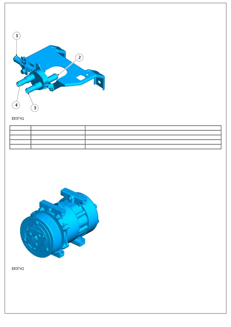
WATER VALVE

Item

Part Number

Description

1

-

Return from heater matrix

2

-

Supply to heater matrix

3

-

Supply from engine cooling system

4

-

Return to engine cooling system

The water valve is mounted at the rear of the engine compartment. A Bowden cable acts on a lever on the rear face of

the water valve to vary the flow of hot engine coolant into the heater matrix. When the water valve is fully closed, no

engine coolant is allowed to flow into the heater matrix. In this instance, engine coolant will flow into the water valve

through inlet (3) and immediately out through the return (4).

AIR CONDITIONING COMPRESSOR

The A/C compressor circulates refrigerant around the system by compressing low pressure, low temperature vapor from

the evaporator and discharging the resultant high pressure, high temperature vapor to the condenser.

The A/C compressor is a constant displacement unit which is driven by the engine accessory drive belt. To protect the

system from excessive pressure, a pressure relief valve is installed in the outlet side of the A/C compressor. The

pressure relief valve vents excess pressure into the engine compartment.

Compressor clutch engagement is controlled by the ECM. The ECM receives system pressure inputs from the refrigerant

pressure switch and system temperature inputs from the thermostatic switch. The ECM will de-energize the A/C

compressor clutch relay on receipt of a pressure reading above or below the system limits, or a temperature reading

that may cause the evaporator to freeze. For more information, refer to the 'Air Conditioning Refrigerant Pressure

Switch' and 'Thermostatic Switch' sections below.

AIR CONDITIONING CONDENSER

The condenser transfers heat from the refrigerant to the surrounding air to convert the high pressure vapor from the

compressor into a liquid. The condenser is installed immediately in front of the radiator and is held in place by 3

brackets; 1 at the top, 2 at the bottom.

The RH end of the condenser provides a connection to the high pressure line from the A/C compressor. The LH end of

the condenser provides a connection to the low pressure line to the receiver drier.

AIR CONDITIONING RECEIVER DRIER

The receiver drier is mounted in the LH front corner of the engine compartment and removes solid impurities and

moisture from the refrigerant. It also provides a reservoir for liquid refrigerant to accommodate changes of heat load at

the evaporator.

Refrigerant entering the receiver drier passes through a filter and a desiccant pack, then collects in the base of the unit

before flowing through the outlet pipe to the evaporator.

AIR CONDITIONING EVAPORATOR

The evaporator is installed in the heater assembly. Liquid refrigerant enters the evaporator and expands, absorbing large

quantities of heat as it changes state to a gas.

Most of the moisture in the air passing through the evaporator condenses into water, which drains out of the vehicle by

passing through a drain tube to the underside of the vehicle.

AIR CONDITIONING THERMOSTATIC EXPANSION VALVE

Item

Part Number

Description

1

-

Metering valve

2

-

Housing

3

-

Diaphragm

4

-

Temperature sensor

5

-

Outlet passage from evaporator

6

-

Inlet passage to evaporator

The thermostatic expansion valve meters the flow of refrigerant into the evaporator, to match the refrigerant flow with

the heat load of the air passing through the evaporator.

The thermostatic expansion valve is a block type valve located behind the heater assembly, and attached to the inlet

and outlet ports of the evaporator. The thermostatic expansion valve consists of an aluminum housing containing inlet

and outlet passages. A ball and spring metering valve is installed in the inlet passage and a temperature sensor is

installed in the outlet passage. The temperature sensor consists of a temperature sensitive tube connected to a

diaphragm. The bottom end of the temperature sensitive tube acts on the ball of the metering valve. Pressure on top of

the diaphragm is controlled by the evaporator outlet temperature conducted through the temperature sensitive tube. The

bottom of the diaphragm senses evaporator outlet pressure.

Liquid refrigerant flows through the metering valve into the evaporator. The restriction across the metering valve

reduces the pressure and temperature of the refrigerant. The restriction also changes the liquid stream of refrigerant

into a fine spray, to improve the evaporation process. As the refrigerant passes through the evaporator, it absorbs heat

from the air flowing through the evaporator. The increase in temperature causes the refrigerant to vaporize and increase

in pressure.

The temperature and pressure of the refrigerant leaving the evaporator acts on the diaphragm and temperature

sensitive tube, which regulate the metering valve opening and so control the volume of refrigerant flowing through the

evaporator. The warmer the air flowing through the evaporator, the more heat available to evaporate refrigerant and

thus the greater volume of refrigerant allowed through the metering valve.

AIR CONDITIONING REFRIGERANT PRESSURE SWITCH

The refrigerant pressure switch is mounted monitors the high pressure side of the A/C system. The switch monitors 3

pressure ranges; high, medium and low. The pressure of refrigerant inside the system is provided to the ECM, which

controls operation of the A/C compressor accordingly.

The pressure ranges monitored by the switch are as follows:

Pressure Range

Upper Limit (bar)

Lower Limit (bar)

High

32

6

Medium

15.5

12.5

Low

2.3

2

If the pressure in the system falls below 2 bar, or rises above 32 bar, the ECM will suspend A/C compressor operation

by de-energizing the main relay, which subsequently de-energizes the A/C compressor clutch relay.

AIR CONDITIONING THERMOSTATIC SWITCH

The thermostatic switch is mounted on the underside of the heater assembly and measures the temperature of the air

coming off the A/C evaporator. This temperature value is fed back to the ECM which controls operation of the A/C

compressor accordingly.

The ECM will suspend A/C compressor operation if the temperature of the air coming off the evaporator drops to 1°C

(34 °F). This prevents the evaporator from freezing. The ECM will re-instate A/C compressor operation when the

temperature of the air coming off the evaporator rises to 3.5°C (38°F).

CONTROL DIAGRAM

• NOTE: A = Hardwired


Content   ..  199  200  201  202   ..