Defender. Manual - part 198


  Index      Land Rover     Land Rover Defender - service manual 2007 year


Search            


Content   ..  196  197  198  199   ..


Defender. Manual - part 198


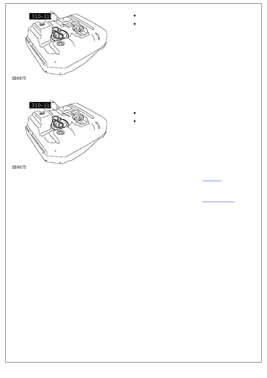
4. Remove the fuel level sender.

Using the special tool, remove the locking ring.

Remove and discard the seal.

Installation

1. NOTE: Clean the component mating faces.

Install the fuel level sender.

Install a new seal.

Using the special tool, tighten the locking ring to 35 Nm

(26 lb.ft).

2. Install the fuel tank. 

For additional information, refer to: 

Fuel Tank

 (310-01 Fuel

Tank and Lines - 2.4L Duratorq-TDCi HPCR (103kW/140PS) -

Puma, Removal and Installation).

3. Connect the battery ground cable. 

For additional information, refer to: 

Battery Connect

 (414-01

Battery, Mounting and Cables, General Procedures).

Fuel Tank and Lines - 2.4L Duratorq-TDCi HPCR (103kW/140PS) - Puma -

Fuel Tank

Removal and Installation

Special Tool(s)

Powertrain assembly jack

HTJ-1200-02

Wrench, Fuel tank

310-118

Removal

• WARNINGS:

 After carrying out repairs, the fuel system must be checked visually for leaks. Failure to follow this instruction

may result in personal injury.

 Do not carry or operate cellular phones when working on or near any fuel related components. Highly flammable

vapors are always present and may ignite. Failure to follow these instructions may result in personal injury.

 Do not smoke or carry lighted tobacco or open flame of any type when working on or near any fuel related

components. Highly flammable vapors are always present and may ignite. Failure to follow these instructions may result

in personal injury.

 If fuel contacts the eyes, flush the eyes with cold water or eyewash solution and seek immediate medical

attention.

 This procedure involves fuel handling. Be prepared for fuel spillage at all times and always observe fuel handling

precautions. Failure to follow these instructions may result in personal injury.

 Wash hands thoroughly after fuel handling, as prolonged contact may cause irritation. Should irritation develop,

seek medical attention.

• CAUTIONS:

 Diesel fuel injection equipment is manufactured to very precise tolerances and fine clearances. It is therefore

essential that absolute cleanliness is observed when working with these components. Always install blanking plugs to

any open orifices or lines. Failure to follow this instruction may result in foreign matter ingress to the fuel injection

system.

 Make sure the workshop area in which the vehicle is being worked on is as clean and as dust free as possible.

Foreign matter from work on clutches, brakes or from machining or welding operations can contaminate the fuel system

and may result in later malfunction.

1. 

WARNING: Do not work on or under a vehicle

supported only by a jack. Always support the vehicle on safety

stands.

Raise and support the vehicle.

2. Disconnect the battery ground cable. 

For additional information, refer to: 

Battery Disconnect and

Connect

 (414-01 Battery, Mounting and Cables, General

Procedures).

3. 

WARNING: The spilling of fuel is unavoidable during

this operation. Make sure that all necessary precautions are

taken to prevent fire and explosion.

Drain the fuel tank. 

For additional information, refer to: 

Fuel Tank Draining

 (310-

00 Fuel System - General Information, General Procedures).

4. 

CAUTION: Make sure that all openings are sealed.

Use new blanking caps.

Disconnect the fuel tank filler pipe.

Loosen the clip.

5. Release the fuel tank vent line.

Release from the clip.

Cut the cable tie.

6. Using the special tool, support the fuel tank.

7. Lower the fuel tank.

7. Lower the fuel tank.

Remove the 2 bolts.

Remove the 2 nuts.

8. 

CAUTION: Make sure that all openings are sealed. Use

new blanking caps.

Disconnect the fuel filler pipe breather hose.

Release the clip.

9. 

CAUTION: Make sure that all openings are sealed. Use

new blanking caps.

• NOTE: Note the fitted position of fuel lines.

Remove the fuel tank and the fuel tank support bracket.

Disconnect the 2 fuel lines.

Disconnect the electrical connector.

10. NOTE: Do not disassemble further if the component is


Content   ..  196  197  198  199   ..