Defender. Manual - part 77
Item
Part Number
Description
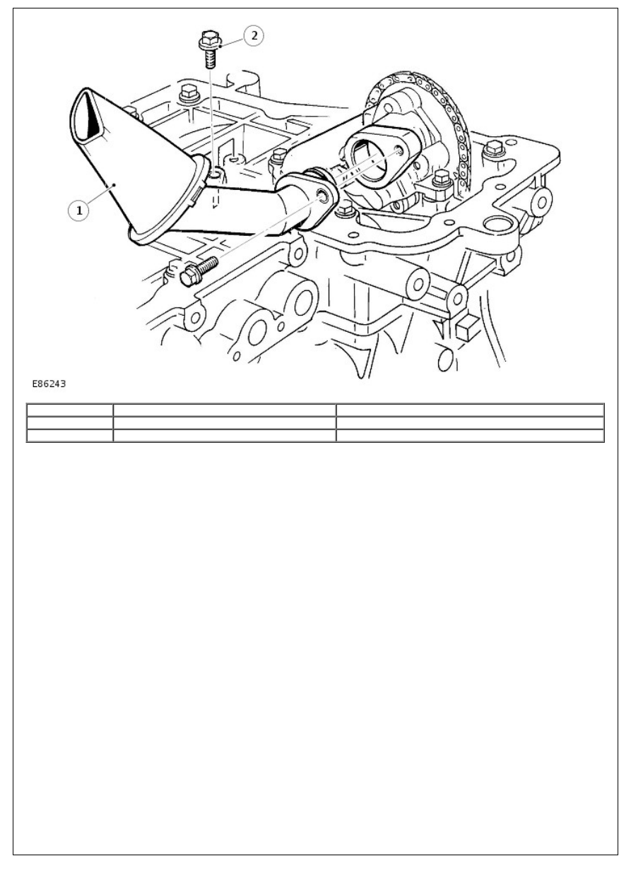
1
-
Oil pick-up pipe
2
-
Bolt (2 off)
The fabricated steel oil pick-up is immersed in the oil reservoir to provide a supply to the oil pump during all normal
vehicle attitudes. A mesh screen in the inlet prevents debris from entering the oil system.
Oil Pump