Defender. Manual - part 71
Item
Part Number
Description
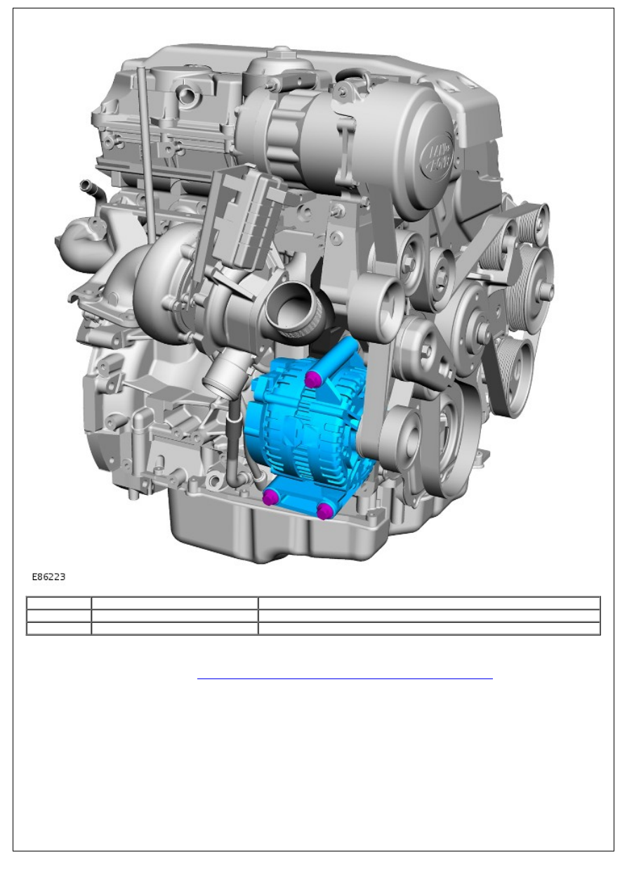
1
-
Generator mounting bracket
2
-
Generator
The generator is located at the front Right Hand (RH) side of the engine on a mounting bracket, which is bolted to the
cylinder block. The accessory drive belt drives the generator pulley, which in turn is driven from the engine crankshaft
pulley.
For additional information, refer to:
Generator - 2.4L Duratorq-TDCi HPCR (103kW/140PS) - Puma
(414-02 Generator
and Regulator - 2.4L Duratorq-TDCi HPCR (103kW/140PS) - Puma, Description and Operation).
Coolant Pump and Vacuum Pump