Defender. Manual - part 43
 

  Index      Land Rover     Land Rover Defender - service manual 2007 year


Search            


Content   ..  41  42  43  44   ..


Defender. Manual - part 43


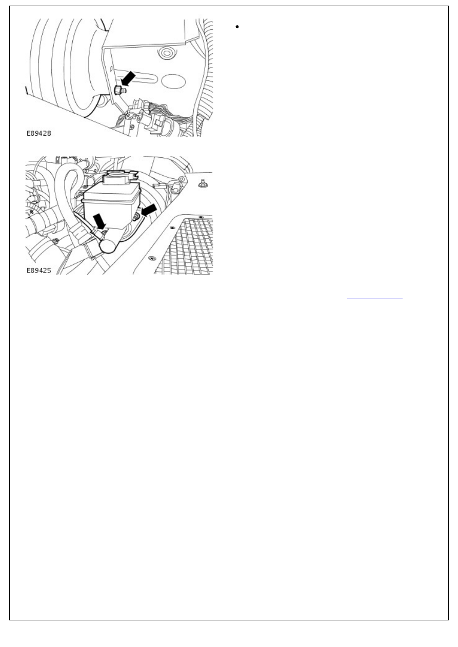
1. To install, reverse the removal procedure.

Tighten to 14 Nm (10 lb.ft).

2. Tighten to 26 Nm (19 lb.ft).

3. Connect the battery ground cable. 

For additional information, refer to: 

Battery Connect

 (414-01

Battery, Mounting and Cables, General Procedures).

Power Brake Actuation - Brake Booster Non-Return Valve

Removal and Installation

Removal

1. Disconnect brake vacuum hose from booster non return

valve.

2. Carefully prise valve out with a screwdriver blade between

valve and grommet. Take care not to exert too much

pressure on the vacuum chamber.

3. Remove rubber grommet but be careful not to allow it to fall

into the vacuum chamber.

4. Check the valve for correct operation; it should not be

possible to pass air through into the booster in direction of

arrow. Do not use compressed air.

Installation

1. Install rubber grommet.
2. Smear ribs of the valve with Lucas Girling rubber grease to

assist assembly, and push valve fully home.

3. Connect vacuum hose to the valve.
4. Road test vehicle.

Power Brake Actuation - Brake Vacuum Pump

Removal and Installation

Removal

1. Remove the cooling fan upper shroud.

Release the 6 screws.

2. NOTE: Cooling fan shown removed for clarity.

Release the tension from the accessory drive belt.

Rotate the accessory drive belt tensioner clockwise.

Displace the accessory drive belt from the brake

vacuum pump pully.

3. Disconnect the brake vacuum pump vacuum pipe.

4. CAUTIONS:

 Make sure that all openings are sealed. Use new

blanking caps.

 Note position of fixing bolts for installation.

Remove the brake vacuum pump.

Remove the 3 bolts.

Remove and discard the gasket.

Installation

1. 

CAUTION: Install fixing bolts to previously noted

positions.

• NOTE: Remove and discard the blanking caps.

• NOTE: Clean the component mating faces.

• NOTE: Install a new gasket.

Install the brake vacuum pump.

Tighten to 23 Nm (17 lb.ft).

2. Connect the brake vacuum pump vacuum pipe.

3. NOTE: Cooling fan shown removed for clarity.

Install the accessory drive belt.

Rotate the accessory drive belt tensioner clockwise.

4. Install the cooling fan upper shroud.

Secure the 6 screws.


Content   ..  41  42  43  44   ..