Defender. Manual - part 19


  Index      Land Rover     Land Rover Defender - service manual 2007 year


Search            


Content   ..  17  18  19  20   ..


Defender. Manual - part 19


Front Suspension - Bump Stop

Removal and Installation

Removal

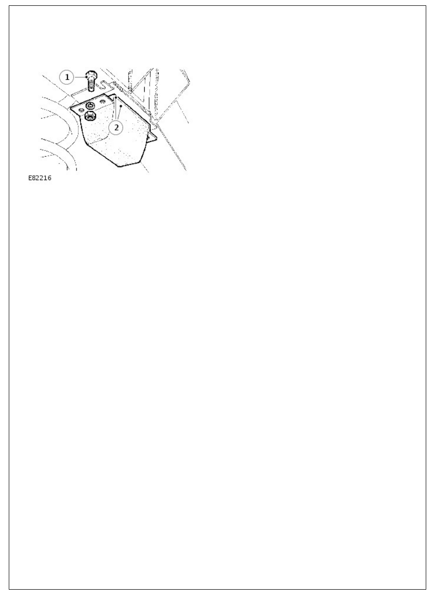
1. Remove the bump stop.

Installation

1. Position bolts in slots in chassis brackets.
2. Install the bump stop, secure with washers and nuts.

Front Suspension - Radius Arm

Removal and Installation

Removal

1. Loosen road wheel retaining nuts.
2. Raise front of vehicle. Support chassis on stands and remove

wheel.

3. Support front axle weight with jack.

4. Remove radius arm to chassis side member fixings.

5. Disconnect track rod at ball joint using tool LRT-57-018.

6. Remove fixings, radius arm to axle.
7. Lower radius arm front end to clear axle and remove from

vehicle.

8. Using suitable length of steel tubing, press out flexible

bushes.

Installation

1. Press in replacement bushes.

CAUTION: When pressing in new bushes press on outer edge of bush and not rubber inner.

2. Instal radius arm to axle mounting.

3. Instal track rod at ball joint.
4. Instal radius arm to chassis. Tighten bolts to 176 Nm (130

lbf.ft).

5. Fully tighten radius arm to axle fixings to 197 Nm (145

lbf.ft).

6. Instal road wheel, remove chassis stands and jack. Tighten

wheel nuts to correct torque:

1. Alloy wheels - 130 Nm (96 lbf.ft)

2. Steel wheels - 100 Nm (80 lbf.ft)

3. Heavy duty wheels - 170 Nm (125 lbf.ft)

Rear Suspension - Rear Suspension

Description and Operation

Rear axle suspension

Item

Part Number

Description

1

-

'A ' frame, upper link assembly

2

-

Lower link

3

-

Coil springs

4

-

Shock absorbers

DESCRIPTION

The rear suspension design locates the rear axle with two round section steel lower link arms and a forged 'A' frame,

upper link assembly. This system allows maximum axle articulation and wheel travel while maintaining roll stiffness and

directional stability.

The link arm is secured by a single retaining nut to the chassis mounting, comprising a rubber bushed bracket, which is

retained by three fixings. A ferrule rubber bush with a single retaining bolt is used to secure the link arm to its axle

mounting.

The upper link assembly is located on the rear differential housing by a pivot ball-pin assembly. Two brackets bolted to

the chassis crossmember support both sides of the 'A' frame of the link assembly, secured by single retaining bolts.

A Boge Hydromat self levelling unit can be fitted, as an option, on 110/130 models to give additional support when the

vehicle is used to carry heavier loads.

Two rubber bearing bushes, with retaining straps, secure the rear of the stabilizer bar, if fitted, to the chassis

mountings, while bushed links support the front of the anti-roll bar to the axle.

Conventional long travel coil springs and hydraulic shock absorbers are used to control body movement. The shock

absorbers are secured to chassis mounting brackets and fabricated lower mountings welded to the rear axle. Retaining

plates are used to secure the coil springs to the axle mounting while fabricated brackets, welded to the chassis, are

used for the upper spring location.


Content   ..  17  18  19  20   ..