Jeep XJ. Manual - part 842
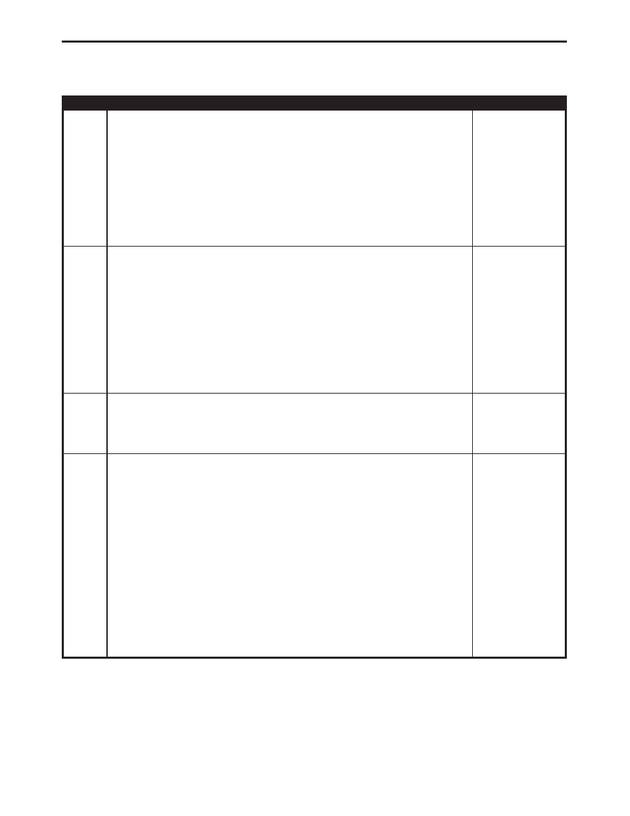
TEST
ACTION
APPLICABILITY
4
Turn the ignition off.
Disconnect the Evap Purge Solenoid harness connector.
Disconnect the PCM harness connector(s).
Note: Check connectors - Clean/repair as necessary.
Measure the resistance of the Evap Purge Solenoid Control Circuit from the
Powertrain Control Module connector to the Evap Purge Solenoid connector.
Is the resistance below 5.0 ohms?
All
Yes
→
No
→
Repair the open Evap Purge Solenoid Control Circuit.
Perform POWERTRAIN VERIFICATION TEST VER - 5.
5
Turn the ignition off.
Disconnect the Evap Purge Solenoid harness connector.
Disconnect the PCM harness connector(s).
Note: Check connectors - Clean/repair as necessary.
Measure the resistance between the Evap Purge Solenoid Control Circuit and ground
(B-).
Is the resistance below 5.0 ohms?
All
Yes
→
Repair the short to ground in the Evap Purge Solenoid Control
Circuit.
Perform POWERTRAIN VERIFICATION TEST VER - 5.
No
→
6
If there are no possible causes remaining, view repair.
All
Repair
Replace the Powertrain Control Module.
Perform POWERTRAIN VERIFICATION TEST VER - 5.
7
At this time, the conditions required to set the DTC are not present.
Note: Use the Freeze Frame Data to help you duplicate the conditions that
set the DTC. Pay particular attention to the DTC set conditions, such as,
VSS, MAP, ECT, and Load.
Note: Visually inspect the related wiring harness. Look for any chafed,
pierced, pinched, or partially broken wires.
Note: Visually inspect the related wire harness connectors. Look for broken,
bent, pushed out, or corroded terminals.
Note: Refer to any technical service bulletins that may apply.
Perform a wiggle test of the Evap Purge Solenoid wiring while the circuit is actuated
with the DRBIII
t. Listen for the solenoid to quit actuating. Also watch for the Good
Trip Counter to change to 0.
Were any problems found?
All
Yes
→
Repair wiring harness/connectors as necessary.
Perform POWERTRAIN VERIFICATION TEST VER - 5.
No
→
Test Complete.
129
DRIVEABILITY - GAS
P0443-EVAP PURGE SOLENOID CIRCUIT —
Continued