Index Jeep Jeep XJ - service repair manual 2001 year
Search
Content .. 585 586 587 588 ..
Jeep XJ. Manual - part 587
10.0
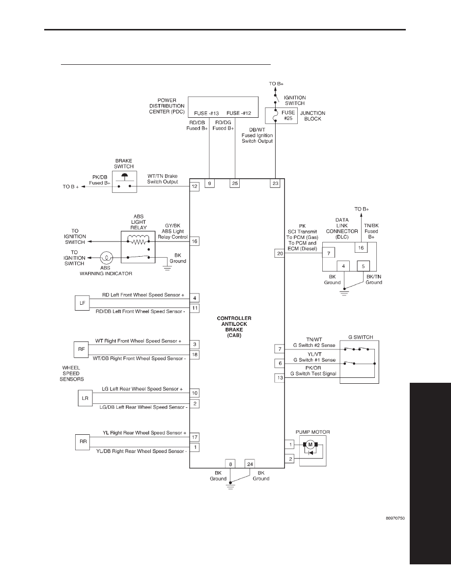
SCHEMATIC
2000 XJ TEVES MARK 2O ANTILOCK BRAKE SYSTEM
S
C
H
E
M
A
T
I
79
SCHEMATICS