Index Jeep Jeep XJ - service repair manual 2001 year
Search
Content .. 565 566 567 568 ..
Jeep XJ. Manual - part 567
10.3
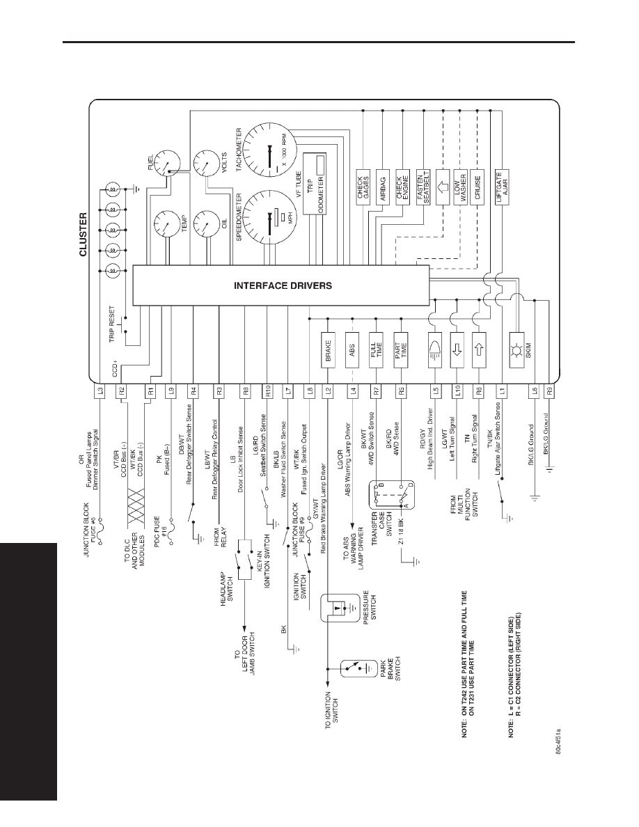
INSTRUMENT CLUSTER
S
C
H
E
M
A
T
I
148
SCHEMATICS