Jeep XJ. Manual - part 528


  Index      Jeep     Jeep XJ - service repair manual 2001 year


Search            


Content   ..  526  527  528  529   ..


Jeep XJ. Manual - part 528


LEAK DETECTION PUMP (LDP)

The LDP is located in the right-rear side of engine

compartment (Fig. 9). The LDP filter is located above
the LDP (Fig. 9). The LDP and LDP filter are
replaced (serviced) as one unit.

REMOVAL

(1) Carefully remove hose at LDP filter.
(2) Remove LDP filter mounting bolt and remove

from vehicle.

(3) Carefully remove vapor/vacuum lines at LDP.
(4) Disconnect electrical connector at LDP.
(5) Remove 2 LDP mounting screws (Fig. 9) and

remove from vehicle.

INSTALLATION

(1) Install LDP to mounting bracket. Tighten

screws to 1 N·m (11 in. lbs.) torque.

(2) Install LDP filter to mounting bracket. Tighten

bolt to 7 N·m (65 in. lbs.) torque.

(3) Carefully install vapor/vacuum lines to LDP,

and install hose to LDP filter. The vapor/vacuum
lines and hoses must be firmly connected.
Check the vapor/vacuum lines at the LDP, LDP
filter and EVAP canister purge solenoid for
damage or leaks. If a leak is present, a Diagnos-
tic Trouble Code (DTC) may be set.

(4) Connect electrical connector to LDP.

SPECIFICATIONS

TORQUE CHART

Description

Torque

EVAP Canister Mounting Nuts (canister-to-

mounting bracket) . . . . . . . . . 5 N·m (45 in. lbs.)

EVAP Canister Mounting Bracket Nuts (mounting

bracket-to-body) . . . . . . . . . . 43 N·m (32 in. lbs.)

EVAP Canister Purge Solenoid Bracket-to-Body

Mounting Bolt . . . . . . . . . . . . 5 N·m (45 in. lbs.)

LDP Mounting Screws . . . . . . . . 1 N·m (11 in. lbs.)

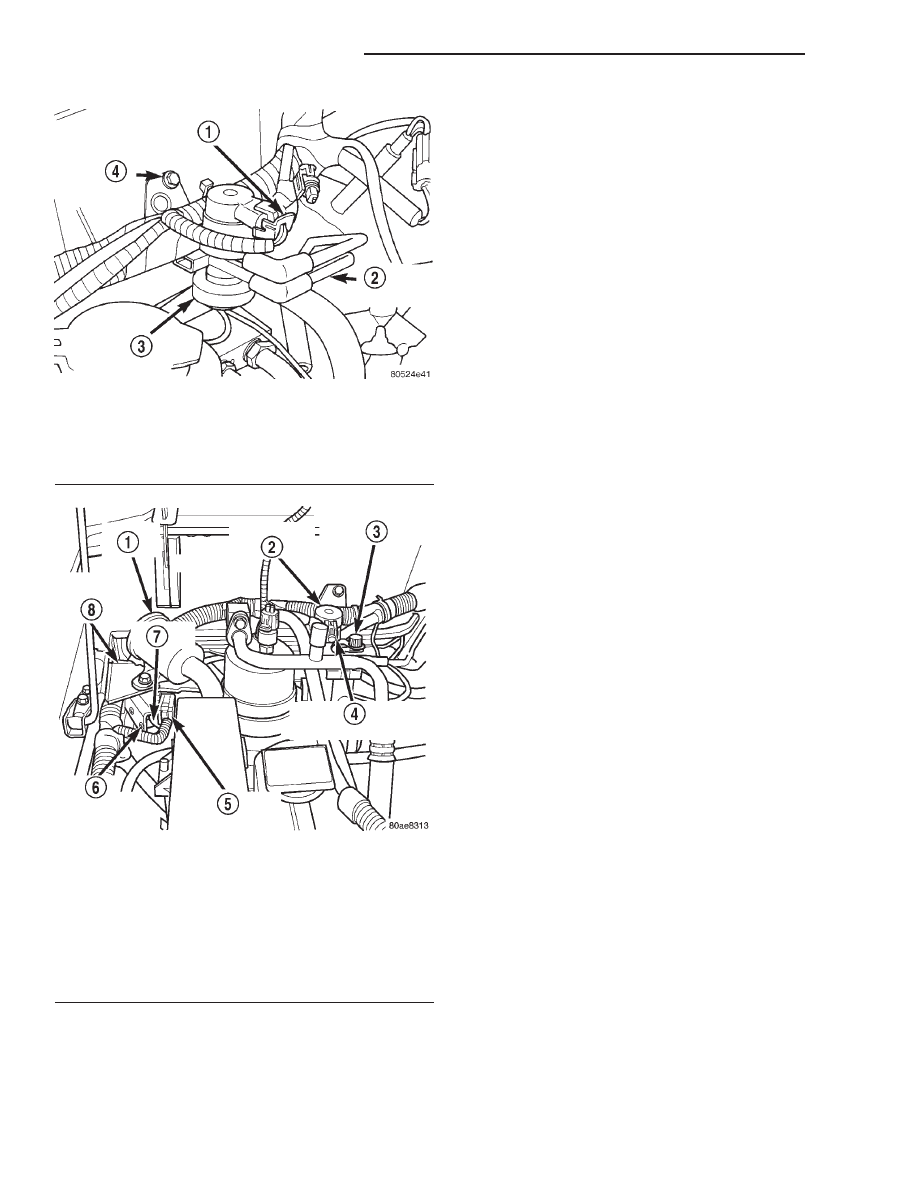
Fig. 8 EVAP Canister Purge Solenoid (Without LDP)

1 – ELECTRICAL CONNECTOR
2 – VACUUM HARNESS
3 – PURGE SOLENOID
4 – MOUNTING BOLT

Fig. 9 EVAP Canister Purge Solenoid (With LDP)

1 – LDP FILTER
2 – EVAP SOLENOID
3 – EVAP SYSTEM TEST PORT
4 – EVAP SOLENOID ELEC. CONNECTOR
5 – LDP ELEC. CONNECTOR
6 – LDP MOUNTING SCREWS (2)
7 – LDP
8 – LDP MOUNTING BRACKET

25 - 28

EMISSION CONTROL SYSTEMS

XJ

REMOVAL AND INSTALLATION (Continued)

EMISSION CONTROL SYSTEM

TABLE OF CONTENTS

page

page

ON-BOARD DIAGNOSTICS—2.5L DIESEL

ENGINE

. . . . . . . . . . . . . . . . . . . . . . . . . . . . . . . . . . 1

EXHAUST EMISSION CONTROLS—2.5L

DIESEL ENGINE. . . . . . . . . . . . . . . . . . . . . . . . . . . 6

ON-BOARD DIAGNOSTICS—2.5L DIESEL ENGINE

TABLE OF CONTENTS

page

page

DESCRIPTION AND OPERATION

EMISSION CONTROL SYSTEM—2.5L DIESEL

ENGINE

. . . . . . . . . . . . . . . . . . . . . . . . . . . . . . . . . 1

DIAGNOSTIC TROUBLE CODES . . . . . . . . . . . . . . 2

DESCRIPTION AND OPERATION

EMISSION CONTROL SYSTEM—2.5L DIESEL
ENGINE

DESCRIPTION

The 2.5L diesel Engine Control Module (ECM) and

Powertrain Control Module (PCM) monitor and con-
trol many different circuits in the fuel injection pump
and engine systems. If the ECM senses a problem
with a monitored circuit that indicates an actual
problem, a Diagnostic Trouble Code (DTC) will be
stored in the PCM’s memory, and eventually may
illuminate the Check Engine Lamp constantly while
the key is on. If the problem is repaired, or is inter-
mittent, the ECM will erase the DTC after 40
warm-up cycles without the the fault detected. A
warm-up cycle consists of starting the vehicle when
the engine is cold, then the engine is warmed up to a
certain temperature, and finally, the engine tempera-
ture falls to a normal operating temperature, then
the key is turned off.

Certain criteria must be met for a DTC to be

entered into ECM memory. The criteria may be a
specific range of engine rpm, engine or fuel tempera-
ture and/or input voltage to the ECM. A DTC indi-
cates that the ECM has identified an abnormal
signal in a circuit or the system. A DTC may indicate
the result of a failure, but never identify the failed
component directly.

There are several operating conditions that the

ECM does not monitor and set a DTC for. Refer to
the following Monitored Circuits and Non–Monitored
Circuits in this section.

ECM MONITORED SYSTEMS

The ECM can detect certain problems in the elec-

trical system.

Open or Shorted Circuit – The ECM will not

distinguish between an open or a short to ground,
however the ECM can determine if the circuit is
shorted to voltage.

Output Device Current Flow – The ECM senses

whether the output devices are electrically connected.

If there is a problem with the circuit, the ECM

senses whether the circuit is open, shorted to ground
(–), or shorted to (+) voltage.

ECM NON–MONITORED SYSTEMS

The ECM does not monitor the following circuits,

systems or conditions that could have malfunctions
that result in driveability problems. A DTC will not
be displayed for these conditions.

Fuel Pressure: Fuel pressure is controlled by the

fuel injection pump. The ECM cannot detect fuel
pressure problems in this component. The ECM does
a comparison analysis of fuel quantity, fuel timing,
fuel temperature, and control sleeve sensor inputs to
determine if a fuel problem exists.

Cylinder Compression: The ECM cannot detect

uneven, low, or high engine cylinder compression.

XJ

EMISSION CONTROL SYSTEM

25 - 1

2000 JEEP CHEROKEE

Exhaust System: The ECM cannot detect a

plugged, restricted or leaking exhaust system.

Fuel Injector Malfunctions: The ECM cannot

determine if the fuel injector is clogged, or the wrong
injector is installed. The fuel injectors on the diesel
engine are not controlled by the ECM, although a
defective needle movement sensor in the #1 injector
is monitored by the ECM.

Vacuum Assist: Leaks or restrictions in the vac-

uum circuits of the Exhaust Gas Recirculation Sys-
tem (EGR) are not monitored by the ECM.

ECM System Ground: The ECM cannot deter-

mine a poor system ground. However, a DTC may be
generated as a result of this condition.

ECM/PCM Connector Engagement: The ECM

cannot determine spread or damaged connector pins.
However, a DTC may be generated as a result of this
condition.

HIGH AND LOW LIMITS

The ECM compares input signals from each input

device. It has high and low limits that are pro-
grammed into it for that device. If the inputs are not
within specifications and other DTC criteria are met,
a DTC will be stored in memory. Other DTC criteria
might include engine rpm limits or input voltages
from other sensors or switches. The other inputs
might have to be sensed by the ECM when it senses
a high or low input voltage from the control system
device in question.

DIAGNOSTIC TROUBLE CODES

DESCRIPTION

On the following pages, a list of DTC’s is provided

for the 2.5L diesel engine. A DTC indicates that the
ECM has recognized an abnormal signal in a circuit
or the system. A DTC may indicate the result of a
failure, but most likely will not identify the failed
component directly.

ACCESSING DIAGNOSTIC TROUBLE CODES

A stored DTC can be displayed through the use of

the DRB III

t scan tool. The DRB IIIt connects to the

data link connector. The data link connector is
located under the instrument panel near bottom of
the steering column (Fig. 1) (Fig. 2).

ERASING TROUBLE CODES

After the problem has been repaired, use the DRB

III

t scan tool to erase a DTC.

Fig. 1 Data Link Connector Location—LHD

1 – 16–WAY DATA LINK CONNECTOR

Fig. 2 Data Link Connector Location—RHD

1 – DATA LINK CONNECTOR

25 - 2

EMISSION CONTROL SYSTEM

XJ

DESCRIPTION AND OPERATION (Continued)

2000 JEEP CHEROKEE

MSA CONTROLLER DRBIII

CODES

Generic Scan Tool Code

DRB III

T

Scan Tool Display

P0115

Temperature of Engine Coolant SRC High Exceeded

Temperature of Engine Coolant SRC Low Exceeded

P0180

Fuel Temperature Sensor SRC High Exceeded

Fuel Temperature Sensor SRC Low Exceeded

P0235

Turbocharger Boost Sensor Signal High Exceeded

Turbocharger Boost Sensor Signal Low Exceeded

Turbocharger Boost Sensor Supply High Exceeded

Turbocharger Boost Sensor Supply High Exceeded

Turbocharger Boost Sensor Plausibility

P0400

EGR Open Circuit

EGR Short Circuit

P0500

Veh. Speed Sensor PEC Frequency Too High

Veh. Speed Sensor SRC High Exceeded

Veh. Speed Sensor Plausibility

P0725

Engine Speed Sensor Dyn. Plausibility

Engine Speed Sensor Over Speed Recognition

Engine Speed Sensor Static Plausibilty

P1105

Atmosphere Pressure Sensor SRC High Exceeded

Atmosphere Pressure Sensor SRC Low Exceeded

P1110

Air Temp. Sensor SRC High Exceeded

Air Temp. Sensor SRC Low Exceeded

P1201

Needle Movement Sensor SRC High Exceeded

Needle Movement Sensor SRC Low Exceeded

P1220

Fuel Quantity Actuator Neg Gov Deviation Cold

Fuel Quantity Actuator Neg Gov Deviation Warm

Fuel Quantity Actuator Pos Gov Deviation Cold

Fuel Quantity Actuator Pos Gov Deviation Warm

P1225

Control Sleeve Sensor Signal High Exceeded

Control Sleeve Sensor Start End Pos. Not Attained

Control Sleeve Sensor Stop End Pos. Not Attained

P1230

Timing Governing Negative Governor Deviation

Timing Governing Positive Governor Deviation

P1515

Accel. Pedal Sensor Signal High Exceeded

Accel. Pedal Sensor Supply SRC High Exceeded

Accel. Pedal Sensor Supply SRC Low Exceeded

Accel. Pedal Sensor Plausibility

XJ

EMISSION CONTROL SYSTEM

25 - 3

DESCRIPTION AND OPERATION (Continued)

2000 JEEP CHEROKEE


Content   ..  526  527  528  529   ..