Jeep XJ. Manual - part 514


  Index      Jeep     Jeep XJ - service repair manual 2001 year


Search            


Content   ..  512  513  514  515   ..


Jeep XJ. Manual - part 514


felt from the front cover. If the felt is saturated with
oil, the shaft seal is leaking and the compressor must
be replaced.

Check the clutch pulley bearing for roughness or

excessive leakage of grease. Replace the bearing, if
required.

INSTALLATION

(1) Install the clutch field coil and snap ring.
(2) Install the clutch coil lead wire harness retain-

ing clip on the compressor front housing and tighten
the retaining screw.

(3) Align the rotor assembly squarely on the front

compressor housing hub.

(4) Install the pulley bearing assembly with the

installer (Special Tool C-6871) (Fig. 27). Thread the

installer on the shaft, then turn the nut until the
pulley assembly is seated.

(5) Install the external front snap ring with snap

ring pliers. The bevel side of the snap ring must be
facing outward. Press the snap ring to make sure it
is properly seated in the groove.

CAUTION: If the snap ring is not fully seated in the
groove it will vibrate out, resulting in a clutch fail-
ure and severe damage to the front housing of the
compressor.

(6) Install the compressor shaft key and the origi-

nal clutch shims on the compressor shaft.

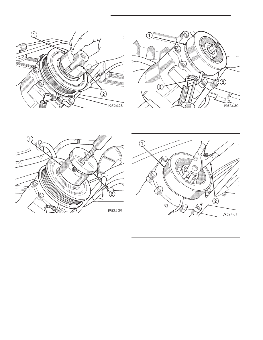
Fig. 23 Shaft Protector and Puller

1 – PULLER JAW
2 – SHAFT PROTECTOR

Fig. 24 Install Puller Plate

1 – PULLER JAW
2 – PULLER

Fig. 25 Clutch Coil Lead Wire Harness

1 – COIL
2 – COIL WIRE
3 – RETAINER SCREW

Fig. 26 Clutch Field Coil Snap Ring Remove

1 – COIL
2 – SNAP RING PLIERS

24 - 30

HEATING AND AIR CONDITIONING

XJ

REMOVAL AND INSTALLATION (Continued)

(7) Install the clutch plate with the driver (Special

Tool C-6463) (Fig. 28). Install the shaft hex nut and
tighten to 14.4 N·m (10.5 ft. lbs.).

(8) Check the clutch air gap with a feeler gauge

(Fig. 29). If the air gap does not meet the specifica-
tion, add or subtract shims as required. The air gap
specification is 0.41 to 0.79 millimeter (0.016 to 0.031
inch). If the air gap is not consistent around the cir-
cumference of the clutch, lightly pry up at the mini-
mum variations. Lightly tap down at the points of
maximum variation.

NOTE: The air gap is determined by the spacer
shims. When installing an original, or a new clutch
assembly, try the original shims first. When install-
ing a new clutch onto a compressor that previously

did not have a clutch, use 1.0, 0.50, and 0.13 milli-
meter (0.040, 0.020, and 0.005 inch) shims from the
clutch hardware package that is provided with the
new clutch.

(9) Reverse the remaining removal procedures to

complete the installation.

CLUTCH BREAK-IN

After a new compressor clutch has been installed,

cycle the compressor clutch approximately twenty
times (five seconds on, then five seconds off). During
this procedure, set the heater-A/C control to the
Recirculation Mode, the blower motor switch in the
highest speed position, and the engine speed at 1500
to 2000 rpm. This procedure (burnishing) will seat
the opposing friction surfaces and provide a higher
compressor clutch torque capability.

COMPRESSOR CLUTCH RELAY

(1) Disconnect and isolate the battery negative

cable.

(2) Remove the cover from the Power Distribution

Center (PDC) (Fig. 30).

(3) Refer to the label on the PDC for compressor

clutch relay identification and location.

(4) Unplug the compressor clutch relay from the

PDC.

(5) Install the compressor clutch relay by aligning

the relay terminals with the cavities in the PDC and
pushing the relay firmly into place.

(6) Install the PDC cover.
(7) Connect the battery negative cable.
(8) Test the relay operation.

Fig. 27 Clutch Pulley Install

1 – PULLEY BEARING ASSEMBLY
2 – INSTALLER

Fig. 28 Clutch Plate Driver

1 – CLUTCH PLATE
2 – DRIVER

Fig. 29 Check Clutch Air Gap

1 – FEELER GAUGE

XJ

HEATING AND AIR CONDITIONING

24 - 31

REMOVAL AND INSTALLATION (Continued)

CONDENSER

WARNING: REVIEW THE WARNINGS AND CAU-
TIONS IN THE FRONT OF THIS GROUP BEFORE
PERFORMING THE FOLLOWING OPERATION.

CAUTION: Before removing the condenser, note the
location of each of the radiator and condenser air
seals. These seals are used to direct air through the
condenser and radiator. The air seals must be rein-
stalled in their proper locations in order for the air
conditioning and engine cooling systems to per-
form as designed.

REMOVAL

(1) Disconnect and isolate the battery negative

cable.

(2) Recover the refrigerant from the refrigerant

system. See Refrigerant Recovery in this group for
the procedures.

(3) Disconnect the discharge line refrigerant line

fitting at the condenser inlet. See Refrigerant Line
Coupler in this group for the procedures. Install
plugs in, or tape over all of the opened refrigerant
line fittings.

(4) Disconnect the liquid line (Left-Hand Drive) or

liquid line jumper (Right-Hand Drive) refrigerant

line fitting at the condenser outlet. See Refrigerant
Line Coupler in this group for the procedures. Install
plugs in, or tape over all of the opened refrigerant
line fittings.

(5) Remove the radiator and the condenser from

the vehicle as a unit. Refer to Group 7 - Cooling Sys-
tem for the procedures.

(6) Remove the two nuts that secure the condenser

studs to the upper brackets of the radiator (Fig. 31).

(7) Slide the condenser down from the radiator far

enough for the condenser studs to clear the upper
radiator bracket holes, and for the lower condenser
bracket holes to clear the dowel pins on the bottom of
the radiator.

(8) Remove the condenser from the radiator.

INSTALLATION

(1) Install the holes of the condenser lower brack-

ets over the dowel pins on the bottom of the radiator.

(2) Slide the condenser upwards until both of the

condenser studs are installed through the holes in
the radiator upper brackets. Tighten the mounting
nuts to 5.3 N·m (47 in. lbs.).

(3) Renstall the radiator and condenser unit in the

vehicle. Refer to Group 7 - Cooling System for the
procedures.

(4) Remove the tape or plugs from the refrigerant

line fittings on the condenser outlet and the liquid
line (Left-Hand Drive) or the liquid line jumper
(Right-Hand Drive). Install the liquid line or the liq-

Fig. 30 Power Distribution Center

1 – RIGHT FENDER
2 – BATTERY
3 – POWER DISTRIBUTION CENTER

Fig. 31 Condenser Remove/Install

1 – NUT
2 – RADIATOR
3 – GROMMET
4 – LOWER CROSSMEMBER
5 – CONDENSER
6 – STUDS

24 - 32

HEATING AND AIR CONDITIONING

XJ

REMOVAL AND INSTALLATION (Continued)

uid line jumper to the condenser outlet. See Refriger-
ant Line Coupler in this group for the procedures.

(5) Remove the tape or plugs from the refrigerant

line fittings on the condenser inlet and the discharge
line. Connect the discharge line to the condenser
inlet. See Refrigerant Line Coupler in this group for
the procedures.

(6) Connect the battery negative cable.
(7) Evacuate the refrigerant system. See Refriger-

ant System Evacuate in this group for the proce-
dures.

(8) Charge the refrigerant system. See Refrigerant

System Charge in this group for the procedures.

NOTE: If the condenser is replaced, add 30 millili-
ters (1 fluid ounce) of refrigerant oil to the refriger-
ant system. Use only refrigerant oil of the type
recommended for the compressor in the vehicle.

DUAL FUNCTION HIGH PRESSURE SWITCH/
HIGH PRESSURE CUT-OFF SWITCH

REMOVAL

(1) Disconnect and isolate the battery negative

cable.

(2) Unplug the wire harness connector from the

dual function high pressure switch or the high pres-
sure cut-off switch, which is mounted to a fitting on
the non-flexible section of the discharge line nearest
the compressor.

(3) Unscrew the high pressure switch from the dis-

charge line fitting.

(4) Remove the high pressure switch from the

vehicle.

(5) Remove the O-ring seal from the discharge line

fitting and discard.

INSTALLATION

(1) Lubricate a new O-ring seal with clean refrig-

erant oil and install it on the discharge line fitting.
Use only the specified O-rings as they are made of a
special material for the R-134a system. Use only
refrigerant oil of the type recommended for the com-
pressor in the vehicle.

(2) Install and tighten the high pressure switch on

the discharge line fitting.

(3) Plug the wire harness connector into the high

pressure cut-off switch.

(4) Connect the battery negative cable.

DUCTS AND OUTLETS

WARNING: ON VEHICLES EQUIPPED WITH AIR-
BAGS,

REFER

TO

GROUP

8M

-

PASSIVE

RESTRAINT SYSTEMS BEFORE ATTEMPTING ANY

STEERING

WHEEL,

STEERING

COLUMN,

OR

INSTRUMENT PANEL COMPONENT DIAGNOSIS OR
SERVICE. FAILURE TO TAKE THE PROPER PRE-
CAUTIONS COULD RESULT IN ACCIDENTAL AIR-
BAG DEPLOYMENT AND POSSIBLE PERSONAL
INJURY.

PANEL OUTLET DUCTS

The panel outlet ducts are integral to the instru-

ment panel assembly. Refer to Instrument Panel
Assembly in Group 8E - Instrument Panel Systems
for the procedures.

PANEL OUTLET BARRELS

(1) Use a trim stick or another suitable wide flat-

bladed tool to gently pry the panel outlet barrel out
of the panel outlet housing (Fig. 32). The barrel is
retained by a light snap fit.

(2) To install, position the barrel in the panel out-

let housing and press firmly until the barrel snaps
into place.

DEMISTER OUTLETS

The side window demister outlets are integral to

the instrument panel end caps. Refer to Instrument
Panel End Cap in Group 8E - Instrument Panel Sys-
tems for the procedures.

DEFROST DUCT/DEMISTER ADAPTER

(1) Remove the instrument panel assembly from

the vehicle. Refer to Instrument Panel Assembly in
Group 8E - Instrument Panel Systems for the proce-
dures.

(2) Disconnect the demister hoses from the defrost

duct/demister adapter (Fig. 33).

Fig. 32 Panel Outlet Barrels

1 – DEMISTER OUTLETS
2 – PANEL OUTLET BARRELS

XJ

HEATING AND AIR CONDITIONING

24 - 33

REMOVAL AND INSTALLATION (Continued)


Content   ..  512  513  514  515   ..