Jeep XJ. Manual - part 513


  Index      Jeep     Jeep XJ - service repair manual 2001 year


Search            


Content   ..  511  512  513  514   ..


Jeep XJ. Manual - part 513


lator outlet tube refrigerant line coupler. See Refrig-
erant Line Coupler in this group for the procedures.

(5) Plug the wire harness connector into the low

pressure cycling clutch switch.

(6) Connect the battery negative cable.
(7) Evacuate the refrigerant system. See Refriger-

ant System Evacuate in this group for the proce-
dures.

(8) Charge the refrigerant system. See Refrigerant

System Charge in this group for the procedures.

NOTE: If the accumulator is replaced, add 120 mil-
liliters (4 fluid ounces) of refrigerant oil to the
refrigerant system. Use only refrigerant oil of the
type recommended for the compressor in the vehi-
cle.

BLEND-AIR DOOR MOTOR

WARNING: ON VEHICLES EQUIPPED WITH AIR-
BAGS,

REFER

TO

GROUP

8M

-

PASSIVE

RESTRAINT SYSTEMS BEFORE ATTEMPTING ANY
STEERING

WHEEL,

STEERING

COLUMN,

OR

INSTRUMENT PANEL COMPONENT DIAGNOSIS OR
SERVICE. FAILURE TO TAKE THE PROPER PRE-
CAUTIONS COULD RESULT IN ACCIDENTAL AIR-
BAG DEPLOYMENT AND POSSIBLE PERSONAL
INJURY.

REMOVAL

(1) Disconnect and isolate the battery negative

cable.

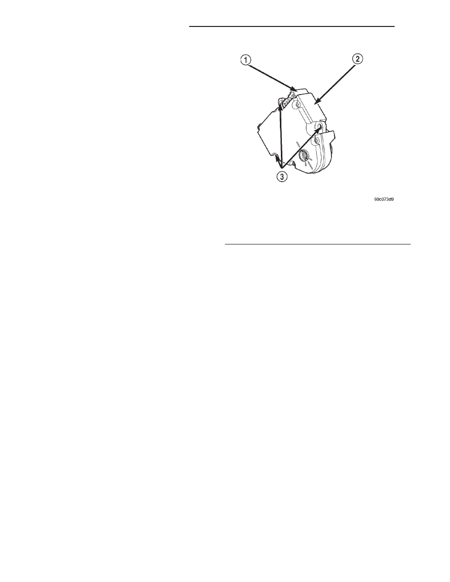
(2) Disconnect the wire connector from the blend-

air door motor.

(3) Remove the screws that secure the blend-air

door motor to the housing (Fig. 15).

(4) Remove the blend-air door motor.

INSTALLATION

(1) Reverse the removal procedures for installa-

tion.

(2) Install and tighten the screws that secures the

blend-air door motor to the housing. Tighten the
mounting screws to 1 N·m (10 in. lbs.).

(3) Connect the battery negative cable.

BLOWER MOTOR

REMOVAL

(1) If the vehicle is equipped with air conditioning,

recover the refrigerant from the refrigerant system.
See Refrigerant Recovery in this group for the proce-
dures.

(2) Disconnect and isolate the battery negative

cable.

(3) If the vehicle is equipped with air conditioning,

the accumulator must be relocated in order to service
the blower motor. This is done by loosening the accu-
mulator retaining band screw and disconnecting the
accumulator inlet tube from the evaporator outlet
tube. The accumulator can then be moved far enough
to access and remove the blower motor. See Accumu-
lator in this group for the procedures.

(4) Unplug the blower motor wire harness connec-

tor (Fig. 16).

(5) Remove the three screws that secure the

blower motor and wheel assembly to the heater-A/C
housing.

(6) Rotate and tilt the blower motor unit as needed

for clearance to remove the blower motor and wheel
from the heater-A/C housing.

INSTALLATION

(1) Align and install the blower motor and wheel

assembly into the heater-A/C housing.

(2) Install and tighten the three screws that secure

the blower motor and wheel assembly to the heater-
A/C housing. Tighten the mounting screws to 2.2
N·m (20 in. lbs.).

(3) Plug in the blower motor wire harness connec-

tor.

(4) If the vehicle is equipped with air conditioning,

connect the accumulator inlet tube to the evaporator
outlet tube and tighten the accumulator retaining
band screw. See Accumulator in this group for the
procedures.

(5) Connect the battery negative cable.

Fig. 15 Blend-Air Door Motor

1 – ELECTRICAL CONNECTOR
2 – BLEND-AIR DOOR MOTOR
3 – SCREW MOUNTING POINTS

24 - 26

HEATING AND AIR CONDITIONING

XJ

REMOVAL AND INSTALLATION (Continued)

(6) If the vehicle is equipped with air conditioning,

evacuate the refrigerant system. See Refrigerant Sys-
tem Evacuate in this group for the procedures.

(7) If the vehicle is equipped with air conditioning,

charge the refrigerant system. See Refrigerant Sys-
tem Charge in this group for the procedures.

BLOWER MOTOR RELAY

WARNING: ON VEHICLES EQUIPPED WITH AIR-
BAGS,

REFER

TO

GROUP

8M

-

PASSIVE

RESTRAINT SYSTEMS BEFORE ATTEMPTING ANY
STEERING

WHEEL,

STEERING

COLUMN,

OR

INSTRUMENT PANEL COMPONENT DIAGNOSIS OR
SERVICE. FAILURE TO TAKE THE PROPER PRE-
CAUTIONS COULD RESULT IN ACCIDENTAL AIR-
BAG DEPLOYMENT AND POSSIBLE PERSONAL
INJURY.

(1) Disconnect and isolate the battery negative

cable.

(2) Roll the glove box down from the instrument

panel. Refer to Glove Box in Group 8E - Instrument
Panel Systems for the procedures.

(3) Reach through the instrument panel glove box

opening to locate the blower motor relay (Fig. 17).

(4) Unplug the blower motor relay from its wire

harness connector.

(5) Install the blower motor relay by aligning the

relay terminals with the cavities in the wire harness
connector and pushing the relay firmly into place.

(6) Roll the glove box back up into the instrument

panel. Refer to Glove Box in Group 8E - Instrument
Panel Systems for the procedures.

(7) Connect the battery negative cable.
(8) Test the relay operation.

BLOWER MOTOR RESISTOR

WARNING: ON VEHICLES EQUIPPED WITH AIR-
BAGS,

REFER

TO

GROUP

8M

-

PASSIVE

RESTRAINT SYSTEMS BEFORE ATTEMPTING ANY
STEERING

WHEEL,

STEERING

COLUMN,

OR

INSTRUMENT PANEL COMPONENT DIAGNOSIS OR
SERVICE. FAILURE TO TAKE THE PROPER PRE-
CAUTIONS COULD RESULT IN ACCIDENTAL AIR-
BAG DEPLOYMENT AND POSSIBLE PERSONAL
INJURY.

(1) Disconnect and isolate the battery negative

cable.

(2) Remove the kick cover from the heater-A/C

housing. See Kick Cover in this group for the proce-
dures.

(3) Pull out the lock on the blower motor resistor

wire harness connector to unlock the connector latch
(Fig. 18).

(4) Depress the latch on the blower motor resistor

wire harness connector and unplug the connector
from the resistor.

(5) Remove the two screws that secure the resistor

to the heater-A/C housing.

(6) Remove the resistor from the heater-A/C hous-

ing.

(7) Reverse the removal procedures to install.

Tighten the mounting screws to 2.2 N·m (20 in lbs.).

Fig. 16 Blower Motor Remove/Install

1 – BLOWER MOTOR
2 – WIRE HARNESS CONNECTOR
3 – MOUNTING SCREWS

Fig. 17 Blower Motor Relay Remove/Install

1 – BLOWER MOTOR RELAY
2 – VACUUM HARNESS
3 – HEATER-A/C WIRE HARNESS CONNECTOR
4 – HEATER-A/C HOUSING

XJ

HEATING AND AIR CONDITIONING

24 - 27

REMOVAL AND INSTALLATION (Continued)

COMPRESSOR

The compressor may be removed and repositioned

without disconnecting the refrigerant lines or dis-
charging the refrigerant system. Discharging is not
necessary if servicing the compressor clutch or clutch
coil, the engine, the cylinder head, or the generator.

WARNING: REVIEW THE WARNINGS AND CAU-
TIONS IN THE FRONT OF THIS GROUP BEFORE
PERFORMING THE FOLLOWING OPERATION.

REMOVAL

(1) Recover the refrigerant from the refrigerant

system. See Refrigerant Recovery in this group for
the procedures.

(2) Disconnect and isolate the battery negative

cable.

(3) Remove the serpentine drive belt. Refer to

Group 7 - Cooling System for the procedures.

(4) Unplug the compressor clutch coil wire harness

connector.

(5) Remove the suction and discharge refrigerant

line manifold from the compressor. See Suction and
Discharge Line in this group for the procedures.
Install plugs in, or tape over all of the opened refrig-
erant fittings.

(6) Remove the four bolts that secure the compres-

sor to the mounting bracket (Fig. 19).

(7) Remove the compressor from the mounting

bracket.

INSTALLATION

NOTE: If

a

replacement

compressor

is

being

installed, be certain to check the refrigerant oil
level. See Refrigerant Oil Level in this group for the
procedures. Use only refrigerant oil of the type rec-
ommended for the compressor in the vehicle.

(1) Install the compressor to the mounting bracket.

Tighten the four mounting bolts as follows:

• All 2.5L and 4.0L engines - 27 N·m (20 ft. lbs.)
(2) Remove the tape or plugs from all of the

opened refrigerant line fittings. Install the suction
and discharge line manifold to the compressor. See
Suction and Discharge Line in this group for the pro-
cedures.

(3) Install the serpentine drive belt. Refer to

Group 7 - Cooling System for the procedures.

(4) Plug in the compressor clutch coil wire harness

connector.

(5) Connect the battery negative cable.
(6) Evacuate the refrigerant system. See Refriger-

ant System Evacuate in this group for the proce-
dures.

(7) Charge the refrigerant system. See Refrigerant

System Charge in this group for the procedures.

Fig. 18 Blower Motor Resistor Remove/Install

1 – SCREWS
2 – WIRE HARNESS CONNECTOR
3 – CONNECTOR LOCK
4 – HEATER-A/C HOUSING
5 – BLOWER MOTOR RESISTOR

Fig. 19 Compressor Remove/Install - All 2.5L/4.0L

Engines

1 – BOLT
2 – MOUNTING BRACKET
3 – ENGINE
4 – COMPRESSOR

24 - 28

HEATING AND AIR CONDITIONING

XJ

REMOVAL AND INSTALLATION (Continued)

COMPRESSOR CLUTCH

The refrigerant system can remain fully-charged

during compressor clutch, pulley, or coil replacement.
The compressor clutch can be serviced in the vehicle.

REMOVAL

(1) Disconnect and isolate the battery negative

cable.

(2) Remove the serpentine drive belt. Refer to

Group 7 - Cooling System for the procedures.

(3) Unplug the compressor clutch coil wire harness

connector.

(4) Remove the four bolts that secure the compres-

sor to the mounting bracket.

(5) Remove the compressor from the mounting

bracket. Support the compressor in the engine com-
partment while servicing the clutch.

(6) Insert the two pins of the spanner wrench

(Special Tool C-4489) into the holes of the clutch
plate. Hold the clutch plate stationary and remove
the hex nut (Fig. 20).

(7) Remove the clutch plate with a puller (Special

Tool C-6461) (Fig. 21).

(8) Remove the compressor shaft key and the

clutch shims.

(9) Remove the external front housing snap ring

with snap ring pliers (Fig. 22).

(10) Install the lip of the rotor puller (Special Tool

C-6141-1) into the snap ring groove exposed in the
previous step, and install the shaft protector (Special
Tool C-6141-2) (Fig. 23).

(11) Install the puller through-bolts (Special Tool

C-6461) through the puller flange and into the jaws
of the rotor puller and tighten (Fig. 24). Turn the

puller center bolt clockwise until the rotor pulley is
free.

(12) Remove the screw and retainer from the

clutch coil lead wire harness on the compressor front
housing (Fig. 25).

(13) Remove the snap ring from the compressor

hub and remove the clutch field coil (Fig. 26). Slide
the clutch field coil off of the compressor hub.

INSPECTION

Examine the friction surfaces of the clutch pulley

and the front plate for wear. The pulley and front
plate should be replaced if there is excessive wear or
scoring.

If the friction surfaces are oily, inspect the shaft

and nose area of the compressor for oil. Remove the

Fig. 20 Clutch Nut Remove

1 – CLUTCH PLATE
2 – SPANNER

Fig. 21 Clutch Plate Remove

1 – CLUTCH PLATE PULLER
2 – CLUTCH PLATE

Fig. 22 External Snap Ring Remove

1 – PULLEY
2 – SNAP RING PLIERS

XJ

HEATING AND AIR CONDITIONING

24 - 29

REMOVAL AND INSTALLATION (Continued)


Content   ..  511  512  513  514   ..