Jeep XJ. Manual - part 466


  Index      Jeep     Jeep XJ - service repair manual 2001 year


Search            


Content   ..  464  465  466  467   ..


Jeep XJ. Manual - part 466


(4) Install drive sprocket snap-ring (Fig. 84).

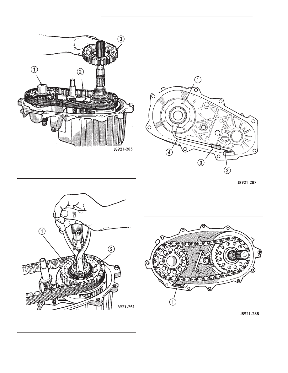
OIL PUMP AND REAR CASE INSTALLATION

(1) Insert oil pickup tube in oil pump and attach

oil screen and connector hose to pickup tube. Then
install assembled pump, tube and screen in rear case
(Fig. 85). Be sure screen is seated in case slot as
shown.

(2) Install magnet in front case pocket (Fig. 86).

Fig. 83 Drive Chain And Sprocket Installation

1 – FRONT OUTPUT SHAFT
2 – DRIVE CHAIN
3 – DRIVE SPROCKET

Fig. 84 Drive Sprocket Snap-Ring Installation

1 – DRIVE SPROCKET
2 – DRIVE SPROCKET SNAP RING

Fig. 85 Oil Screen And Pickup Tube Installation

1 – OIL PUMP
2 – OIL SCREEN
3 – CONNECTOR
4 – PICKUP TUBE

Fig. 86 Installing Case Magnet

1 – MAGNET

21 - 400

NV242 TRANSFER CASE

XJ

DISASSEMBLY AND ASSEMBLY (Continued)

(3) Apply 3 mm (1/8 in.) wide bead of Mopar gas-

ket maker or silicone adhesive sealer to seal surface
of front case.

(4) Align and install rear case on front case. Be

sure case locating dowels are in place and that main-
shaft splines are engaged in oil pump inner gear.

(5) Install and tighten front case-to-rear case bolts

to 41 N·m (30 ft. lbs.) torque. Be sure to install a
washer under each bolt used at case dowel
locations.

REAR RETAINER INSTALLATION

(1) Remove rear bearing in retainer using Installer

8128 and Handle C-4171.

(2) Install rear bearing in retainer with Tools

C-4171 and 5064 (Fig. 87).

(3) Install rear bearing O. D. retaining ring with

snap-ring pliers (Fig. 88). Be sure retaining ring is
fully seated in retainer groove.

(4) Apply bead of Mopar

t Sealer P/N 82300234, or

Loctite

y Ultra Gray, to mating surface of rear

retainer. Sealer bead should be a maximum of 3/16
in.

(5) Install rear retainer on rear case. Tighten

retainer bolts to 20–27 N·m (15–20 ft. lbs.) torque.

(6) Install rear bearing I. D. retaining ring and

spacer on output shaft.

(7) Apply liberal quantity of petroleum jelly to new

rear seal and to output shaft. Petroleum jelly is
needed to protect seal lips during installation.

(8) Slide seal onto Seal Protector 6992 (Fig. 89).

Slide seal protector and seal onto output shaft.

(9) Slide Installer C-4076-B onto seal protector

with the recessed side of the tool toward the seal.

Drive seal into rear bearing retainer with Installer
C-4076-B and Handle MD-998323 (Fig. 90).

(10) Install rear slinger with Installer 8408.
(11) Install boot on output shaft slinger and crimp

retaining clamp with tool C-4975-A (Fig. 91).

FRONT YOKE AND SWITCH INSTALLATION

(1) Install indicator switch in front case. Tighten

switch to 20–34 N·m (15–25 ft. lbs.) torque.

(2) Lubricate yoke hub with transmission fluid and

install yoke on front shaft.

(3) Install new seal washer on front shaft.
(4) Install yoke on front shaft. Secure yoke with

new nut.

Fig. 87 Installing Rear Bearing In Retainer

1 – SPECIAL TOOL C-4171
2 – SPECIAL TOOL 5064
3 – REAR RETAINER

Fig. 88 Rear Bearing Retaining Ring Installation

1 – REAR BEARING O. D. RETAINING RING
2 – SNAP RING PLIERS

Fig. 89 Output Shaft Seal and Protector

1 – OUTPUT SHAFT SEAL
2 – SPECIAL TOOL 6992
3 – TRANSFER CASE

XJ

NV242 TRANSFER CASE

21 - 401

DISASSEMBLY AND ASSEMBLY (Continued)

CLEANING AND INSPECTION

NV242 TRANSFER CASE

Clean the transfer case parts with a standard

parts cleaning solvent. Remove all traces of sealer
from the cases and retainers with a scraper and all
purpose cleaner. Use compressed air to remove sol-
vent residue from oil feed passages in the case
halves, retainers, gears, and shafts.

The oil pickup screen can be cleaned with solvent.

Shake excess solvent from the screen after cleaning
and allow it to air dry. Do not use compressed air.

MAINSHAFT/SPROCKET/HUB INSPECTION

Inspect the splines on the hub and shaft and the

teeth on the sprocket. Minor nicks and scratches can
be smoothed with an oilstone. However, replace any
part is damaged.

Check the contact surfaces in the sprocket bore

and on the mainshaft. Minor nicks and scratches can
be smoothed with 320–400 grit emery cloth but do
not try to salvage the shaft if nicks or wear is severe.

INPUT GEAR AND PLANETARY CARRIER

Check the teeth on the gear (Fig. 92). Minor nicks

can be dressed off with an oilstone but replace the
gear if any teeth are broken, cracked, or chipped. The
bearing surface on the gear can be smoothed with
300–400 grit emery cloth if necessary.

Examine the carrier body and pinion gears for

wear or damage. The carrier will have to be replaced
as an assembly if the body, pinion pins, or pinion
gears are damaged.

Check the lock ring and both thrust washers for

wear or cracks. Replace them if necessary. Also
replace the lock retaining ring if bent, distorted, or
broken.

SHIFT FORKS/HUBS/SLEEVES

Check condition of the shift forks and mode fork

shift rail (Fig. 93). Minor nicks on the shift rail can
be smoothed with 320–400 grit emery cloth.

Inspect the shift fork wear pads. The mode fork

pads are serviceable and can be replaced if necessary.
The range fork pads are also serviceable.

Check both of the sleeves for wear or damage,

especially on the interior teeth. Replace the sleeves if
wear or damage is evident.

REAR RETAINER/BEARING/ SEAL/SLINGER/BOOT

Inspect the retainer components (Fig. 94). Replace

the bearing if rough or noisy. Check the retainer for
cracks or wear in the bearing bore. Clean the
retainer sealing surfaces with a scraper and all pur-
pose cleaner. This will ensure proper adhesion of the
sealer during reassembly.

Replace the slinger and seal outright; do not reuse

either part.

Inspect the retaining rings and washers. Replace

any part if distorted, bent, or broken. Reuse is not
recommended. Also replace the boot if cut or torn.
Replace the boot band clamps, do not reuse them.

REAR OUTPUT SHAFT/YOKE/DRIVE CHAIN

Check condition of the seal contact surfaces of the

yoke slinger (Fig. 95). This surface must be clean and
smooth to ensure proper seal life. Replace the yoke
nut and seal washer as neither part should be
reused.

Fig. 91 Slinger Boot Installation

1 – SPECIAL TOOL C-4975–A
2 – SLINGER
3 – BOOT
4 – CLAMP

Fig. 90 Rear Seal Installation

1 – SPECIAL TOOL C-4076–B
2 – SPECIAL TOOL MD998323
3 – TRANSFER CASE

21 - 402

NV242 TRANSFER CASE

XJ

DISASSEMBLY AND ASSEMBLY (Continued)

Inspect the shaft threads, sprocket teeth, and bear-

ing surfaces. Minor nicks on the teeth can be
smoothed with an oilstone. Use 320–400 grit emery
to smooth minor scratches on the shaft bearing sur-
faces. Rough threads on the shaft can be chased if
necessary. Replace the shaft if the threads are dam-
aged, bearing surfaces are scored, or if any sprocket
teeth are cracked or broken.

Examine the drive chain and shaft bearings.

Replace the chain and both sprockets if the chain is
stretched, distorted, or if any of the links bind.
Replace the bearings if rough, or noisy.

LOW RANGE ANNULUS GEAR

Inspect annulus gear condition carefully. The gear

is only serviced as part of the front case. If the gear
is damaged, it will be necessary to replace the gear
and front case as an assembly. Do not attempt to
remove the gear (Fig. 96).

FRONT-REAR CASES AND FRONT RETAINER

Inspect the cases and retainer for wear and dam-

age. Clean the sealing surfaces with a scraper and all
purpose cleaner. This will ensure proper sealer adhe-
sion at assembly. Replace the input retainer seal; do
not reuse it.

Check case condition. If leaks were a problem, look

for gouges and severe scoring of case sealing sur-
faces. Also make sure the front case mounting studs
are in good condition.

Check the front case mounting studs and vent

tube. The tube can be secured with Loctite

y 271 or

680 if loose. The stud threads can be cleaned up with
a die if necessary. Also check condition of the fill/
drain plug threads in the rear case. The threads can
be repaired with a thread chaser or tap if necessary.
Or the threads can be repaired with Helicoil stainless
steel inserts if required.

Fig. 92 Input Gear And Carrier Components

1 – PLANETARY CARRIER
2 – REAR THRUST WASHER
3 – FRONT THRUST WASHER

4 – CARRIER LOCK RING
5 – CARRIER LOCK RETAINING RING
6 – INPUT GEAR

Fig. 93 Shift forks

1 – RANGE FORK
2 – MODE FORK AND RAIL
3 – MODE SPRING

XJ

NV242 TRANSFER CASE

21 - 403

CLEANING AND INSPECTION (Continued)


Content   ..  464  465  466  467   ..