Jeep XJ. Manual - part 446


  Index      Jeep     Jeep XJ - service repair manual 2001 year


Search            


Content   ..  444  445  446  447   ..


Jeep XJ. Manual - part 446


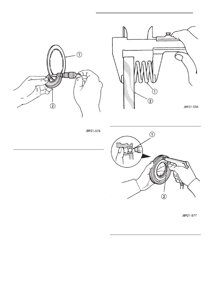
(20) Measure clutch disc thickness (Fig. 260). Min-

imum allowable thickness is 1.51 mm (0.0595 in.).
Replace clutch pack if any disc falls below specified
minimum thickness.

(21) Measure free length of piston return springs

with springs mounted in retainer (Fig. 261). Length
should be 19.47 mm (0.767 in.). Replace springs and
retainer if length is incorrect.

(22) Inspect clutch piston check ball (Fig. 262).

Ball should move freely within piston. Check ball
seating by applying low pressure compressed air to
ball feed hole. Ball should seat firmly and not leak
air.

(23) Measure inside diameter of bushing in clutch

drum hub. Maximum allowable diameter is 24.08
mm (0.9480 in.). Replace clutch drum if bushing
inside diameter is greater than specified.

ASSEMBLY

(1) Lubricate bearing and race assembly with

petroleum jelly and install it in clutch drum (Fig.
263). Race side of assembly faces downward and
toward drum. Bearing rollers face up (Fig. 263)

(2) Coat new clutch drum shaft seal rings with

petroleum jelly. Before installing drum shaft seal
rings, squeeze each ring so ring ends overlap (Fig.
264). This tightens ring making clutch installation
easier.

(3) Install seal rings on shaft. Keep rings closed as

tightly as possible during installation. Avoid over-
spreading them.

(4) Mount clutch drum on overdrive support.
(5) Lubricate and install new O–ring on clutch

drum hub (Fig. 257).

Fig. 260 Measuring Clutch Disc Thickness

1 – CLUTCH DISC
2 – MICROMETER

Fig. 261 Checking Return Spring Length

1 – PISTON RETURN SPRINGS
2 – SPRING RETAINER

Fig. 262 Testing Piston Check Ball

1 – PISTON CHECK BALL
2 – USE LOW AIR PRESSURE FOR TEST

21 - 320

AW–4 AUTOMATIC TRANSMISSION

XJ

DISASSEMBLY AND ASSEMBLY (Continued)

(6) Lubricate new clutch piston O–rings with

Mopar Door Ease, or Ru–Glyde. Install rings on
clutch piston and install piston in drum.

(7) Install piston return springs.
(8) Compress piston return springs with Tool 7538

and shop press and install piston snap ring. Be sure
snap ring end gap is not aligned with any notches in
drum.

(9) Install cushion plate in drum. Concave side of

plate faces downward (Fig. 255).

(10) Install clutch discs, plates and retainer (Fig.

265). Install tabbed plate followed by disc until
required number of plates and discs are installed.
Use six plates and discs.

(11) Install clutch pack snap ring.
(12) Recheck clutch piston stroke length using

same method outlined at beginning of disassembly
procedure. If stroke length is not within specified
limits, replace clutch discs.

(13) Lubricate race and bearing with petroleum

jelly and install them in clutch drum (Fig. 266). Be
sure bearing rollers face up and race lip seats in
drum as shown.

(14) Verify bearing and race size.
• Outer diameter of bearing is 46.7 mm (1.839 in).

• Outer diameter of race is 48.9 mm (1.925 in.).

• Inner diameter of bearing and race is 26.0 mm

(1.024 in.).

(15) Mount forward clutch on direct clutch and

check assembled height (Fig. 267). Height should be
70.3 – 71.5 mm (2.767 – 2.815 in.).

Fig. 263 Installing Thrust Bearing And Race

1 – BEARING ROLLERS FACE UP
2 – THRUST BEARING AND RACE
3 – FORWARD CLUTCH

Fig. 264 Installing Clutch Drum Shaft Seal Rings

1 – SEAL RINGS (COMPRESS BEFORE INSTALLATION)
2 – CLUTCH DRUM SHAFT

Fig. 265 Installing Forward Clutch Discs And Plates

1 – RETAINER
2 – CLUTCH PLATES
3 – CLUTCH DISCS

XJ

AW–4 AUTOMATIC TRANSMISSION

21 - 321

DISASSEMBLY AND ASSEMBLY (Continued)

FRONT PLANETARY GEAR

DISASSEMBLY

(1) Remove ring gear from planetary gear (Fig. 268).
(2) Remove front bearing and the two races from

ring gear (Fig. 268).

(3) Remove tabbed thrust race from planetary gear

(Fig. 268).

(4) Remove snap ring attaching planetary gear to

shaft and remove gear.

Fig. 267 Checking Forward Clutch Assembled

Height

1 – DIRECT CLUTCH
2 – APPROXIMATELY 71.2 mm (2.80 in.)
3 – FORWARD CLUTCH

Fig. 268 Front Planetary Gear Components

1 – FORWARD RACE
2 – FRONT PLANETARY RING GEAR
3 – FRONT BEARING
4 – SNAP RING
5 – REAR RACE

6 – REAR BEARING
7 – FRONT PLANETARY GEAR
8 – THRUST RACE
9 – FRONT RACE

Fig. 266 Installing Thrust Bearing And Race

1 – THRUST BEARING AND RACE
2 – CLUTCH DRUM

21 - 322

AW–4 AUTOMATIC TRANSMISSION

XJ

DISASSEMBLY AND ASSEMBLY (Continued)

(5) Remove rear bearing and race from planetary gear.
(6) Measure inside diameter of ring gear bushing.

Maximum allowable diameter is 24.08 mm (0.9480
in.). Replace ring gear if bushing inside diameter is
greater than specified.

(7) Check condition of planetary gear. Replace gear

if teeth are worn, pins are loose, or carrier is cracked,
distorted, or worn.

ASSEMBLY

(1) Lubricate planetary and ring gear bearings and

races with petroleum jelly.

(2) Identify planetary bearings and races before

installation. (Fig. 268). Bearings and races can be
identified by following dimensions:

• Outer diameter of rear bearing is 47.7 mm

(1.878 in.). Inner diameter is 35.5 mm (1.398 in.).

• Outer diameter of rear race 47.6 mm (1.874 in.).

Inner diameter is 33.7 mm (1.327 in.).

• Outer diameter of front race is 53.6 mm (2.110

in.). Inner diameter is 30.5 mm (1.201 in.).

• Outer diameter of front bearing is 47.7 mm

(1.878 in.). Inner diameter is 32.6 (1.283 in.).

• Outer diameter of forward race is 47.0 mm

(1.850 in.). Inner diameter is 26.5 mm 1.043 in.).

(3) Install rear race and bearing in gear (Fig. 269).
(4) Turn planetary over and install thrust race

(Fig. 270).

(5) Install front race and bearing and forward race

in ring gear (Fig. 271).

Fig. 269 Front Planetary Rear Bearing and Race

Installation

1 – REAR BEARING AND RACE
2 – PLANETARY GEAR

Fig. 270 Front Planetary Thrust Race Installation

1 – TABBED THRUST RACE
2 – PLANETARY GEAR

Fig. 271 Front Planetary Front Bearing And Races

Installation

1 – FRONT BEARING AND RACE
2 – FORWARD RACE

XJ

AW–4 AUTOMATIC TRANSMISSION

21 - 323

DISASSEMBLY AND ASSEMBLY (Continued)


Content   ..  444  445  446  447   ..