Jeep XJ. Manual - part 429


  Index      Jeep     Jeep XJ - service repair manual 2001 year


Search            


Content   ..  427  428  429  430   ..


Jeep XJ. Manual - part 429


(19) Connect transmission cooler lines.
(20) Connect transmission throttle cable at engine.
(21) Install new O–ring seal on upper half of

transmission fill tube. Then connect upper and lower
tube halves.

(22) Lower vehicle.
(23) Fill transmission with Mopar

t Dexron IIE/

Mercon automatic transmission fluid.

TORQUE CONVERTER

REMOVAL

(1) Remove transmission and torque converter

from vehicle.

(2) Place a suitable drain pan under the converter

housing end of the transmission.

CAUTION: Verify that transmission is secure on the
lifting device or work surface, the center of gravity
of the transmission will shift when the torque con-
verter is removed creating an unstable condition.

The torque converter is a heavy unit. Use caution

when separating the torque converter from the
transmission.

(3) Pull the torque converter forward until the cen-

ter hub clears the oil pump seal.

(4) Separate the torque converter from the trans-

mission.

INSTALLATION

Check converter hub and drive notches for sharp

edges, burrs, scratches, or nicks. Polish the hub and
notches with 320/400 grit paper or crocus cloth if nec-
essary. The hub must be smooth to avoid damaging
the pump seal at installation.

(1) Lubricate converter hub and oil pump seal lip

with transmission fluid.

(2) Place torque converter in position on transmis-

sion.

CAUTION: Do not damage oil pump seal or bushing
while inserting torque converter into the front of the
transmission.

(3) Align torque converter to oil pump seal open-

ing.

(4) Insert torque converter hub into oil pump.
(5) While pushing torque converter inward, rotate

converter until converter is fully seated in the oil
pump gears.

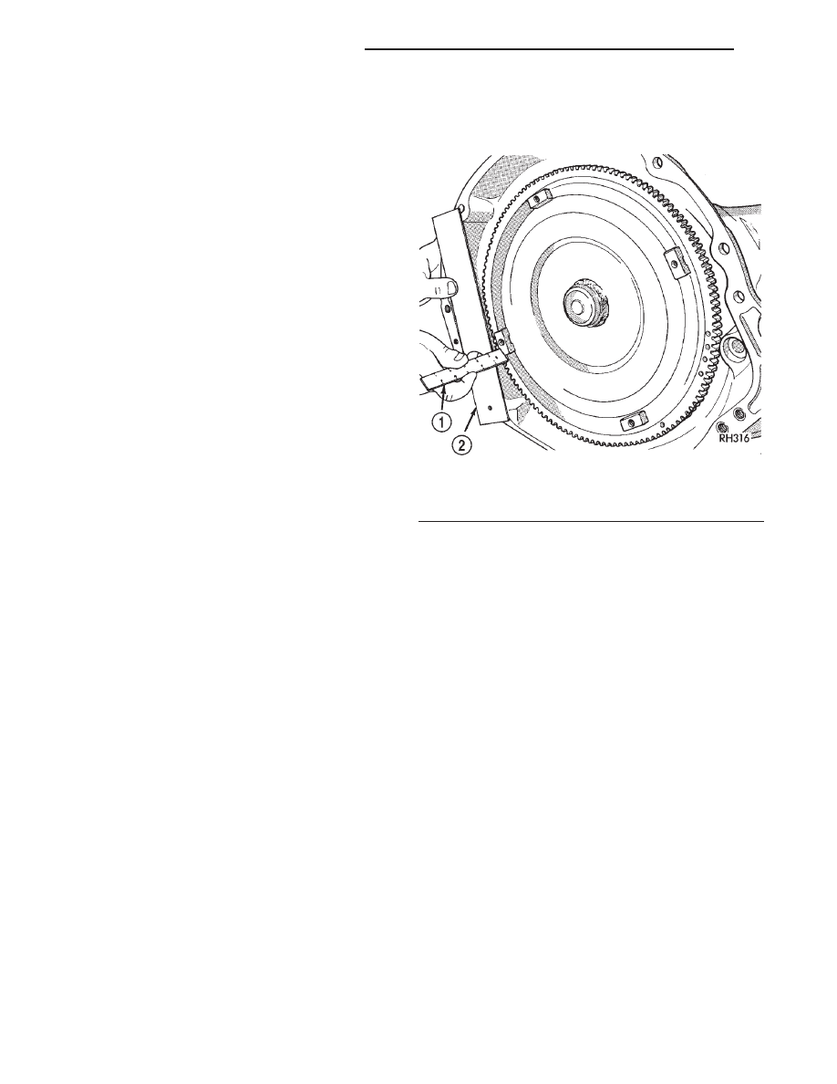
(6) Check converter seating with a scale and

straightedge (Fig. 48). Surface of converter lugs
should be 1/2 in. to rear of straightedge when con-
verter is fully seated.

(7) If necessary, temporarily secure converter with

C-clamp attached to the converter housing.

(8) Install the transmission in the vehicle.
(9) Fill the transmission with the recommended

fluid.

ADAPTER HOUSING SEAL

REMOVAL

(1) Raise vehicle.
(2) Disconnect or remove components necessary to

gain access to seal (e.g. propeller shaft, crossmember,
shift linkage, transfer case, exhaust components,
hoses, wires).

(3) On 4X2 vehicles, remove dust shield from the

adapter housing by tapping gently with a brass drift
and hammer (Fig. 49).

(4) On 4X2 vehicles, remove the adapter housing

seal with Seal Puller 7550.

(5) On 4X4 vehicles, remove the adapter housing

seal using a slide hammer mounted screw.

INSTALLATION

(1) Install new adapter housing seal with Seal

Installer 7888.

(2) On 4X2 vehicles, install dust shield using Spe-

cial Tool D-187-B.

(3) Reinstall components removed to gain access to

seal.

(4) Top off transmission fluid if necessary.

SPEED SENSOR

REMOVAL

(1) Disconnect sensor wire harness connector.

Fig. 48 Checking Torque Converter Seating

1 – SCALE
2 – STRAIGHTEDGE

21 - 252

AW–4 AUTOMATIC TRANSMISSION

XJ

REMOVAL AND INSTALLATION (Continued)

(2) Remove sensor retainer bolt and remove sensor

(Fig. 50).

(3) Remove and discard speed sensor O–ring.

INSTALLATION

(1) Install new O–ring on speed sensor and install

sensor in transmission case.

(2) Install

sensor

bracket

and

retainer

bolt.

Tighten bolt to 7.4 N·m (65 in. lbs.) torque.

(3) Connect sensor wire harness connector.

SPEEDOMETER ADAPTER

Rear axle gear ratio and tire size determine speed-

ometer pinion requirements.

REMOVAL

(1) Raise vehicle.
(2) Disconnect wires from vehicle speed sensor.
(3) Remove adapter clamp and screw (Fig. 51).
(4) Remove speed sensor and speedometer adapter

as assembly.

(5) Remove speed sensor retaining screw and

remove sensor from adapter.

(6) Remove speedometer pinion from adapter.

(7) Inspect sensor and adapter O-rings (Fig. 51).

Remove and discard O-rings if worn or damaged.

(8) Inspect terminal pins in speed sensor. Clean

pins with Mopar

t electrical spray cleaner if dirty or

oxidized. Replace sensor if faulty, or pins are loose,
severely corroded, or damaged.

INSTALLATION

(1) Thoroughly clean adapter flange and adapter

mounting surface in housing. Surfaces must be clean
for proper adapter alignment and speedometer oper-
ation.

(2) Install new O-rings on speed sensor and speed-

ometer adapter if necessary (Fig. 51).

(3) Lubricate sensor and adapter O-rings with

transmission fluid.

(4) Install vehicle speed sensor in speedometer

adapter. Tighten sensor attaching screw to 2-3 N·m
(15-27 in. lbs.) torque.

(5) Install speedometer pinion in adapter.
(6) Count number of teeth on speedometer pinion.

Do this before installing assembly in housing. Then
lubricate pinion teeth with transmission fluid.

(7) Note index numbers on adapter body (Fig. 52).

These numbers will correspond to number of teeth on
pinion.

(8) Install speedometer assembly in housing.
(9) Rotate adapter until required range numbers

are at 6 o’clock position. Be sure range index num-
bers correspond to number of teeth on pinion gear.

Fig. 49 Adapter Housing Seals

1 – 4WD ADAPTER HOUSING
2 – SEAL
3 – BUSHING
4 – OIL TUBE
5 – 2WD EXTENSION HOUSING
6 – SEAL
7 – SPEED SENSOR
8 – SPEED SENSOR

Fig. 50 Transmission Speed Sensor Removal/

Installation

1 – RETAINER BOLT
2 – SPEED SENSOR

XJ

AW–4 AUTOMATIC TRANSMISSION

21 - 253

REMOVAL AND INSTALLATION (Continued)

(10) Install speedometer adapter clamp and retain-

ing screw. Tighten clamp screw to 10-12 N·m (90-110
in. lbs.) torque.

(11) Connect wires to vehicle speed sensor.
(12) Lower vehicle and top off transmission fluid

level, if necessary.

SPEED SENSOR ROTOR-SPEEDOMETER DRIVE
GEAR

REMOVAL

(1) Raise vehicle.
(2) Remove components necessary to gain access to

rotor and drive gear such as propeller shaft, transfer
case, crossmember, and shift linkage.

(3) Disengage wire connector from the output

speed sensor.

(4) Remove the bolt holding the output speed sen-

sor to the adapter housing.

(5) Remove the output speed sensor from the

adapter housing.

(6) Remove the bolts holding the adapter housing

to the transmission case.

(7) Tap the adapter housing at the joint line gently

with a rubber mallet to separate the adapter housing
from the transmission case.

(8) Remove the adapter housing from the trans-

mission case.

(9) Remove speedometer drive gear snap ring (Fig.

53).

(10) Remove

the

speedometer

drive

gear

and

spacer, if equipped.

(11) Remove rotor from the output shaft. It may be

necessary to use a wood dowel or hammer handle
(Fig. 54) to gently pry the rotor from the output

Fig. 51 Speedometer Pinion Adapter Components

1 – SENSOR O-RING
2 – SPEEDOMETER ADAPTER
3 – ADAPTER O-RING

4 – SPEEDOMETER PINION
5 – ADAPTER CLAMP
6 – VEHICLE SPEED SENSOR

ITEM

TORQUE

A

2-3 N·m (15-27 in. lbs.)

B

10-12 N·m (90-110 in. lbs.)

Fig. 52 Index Numbers On Speedometer Pinion

Adapter

1 – SPEEDOMETER ADAPTER
2 – INDEX NUMBER LOCATION

21 - 254

AW–4 AUTOMATIC TRANSMISSION

XJ

REMOVAL AND INSTALLATION (Continued)

shaft. Be sure to retrieve the rotor locating key from
the output shaft or rotor.

INSTALLATION

(1) Clean sealing surfaces of transmission case and

extension/adaptor housing.

(2) Install rotor, spacer (if equipped) and drive

gear on output shaft. Then install drive gear snap
ring (Fig. 53).

(3) Apply 1/8 3/16 inch wide bead of Threebond

t

Liquid Gasket TB1281, P/N 83504038, to transmis-
sion case sealing surface and install extension/
adapter housing on case.

(4) Tighten adaptor housing bolts to 34 N·m (25 ft.

lbs.) torque.

(5) Install components removed to gain access to

rotor and drive gear.

PARK/NEUTRAL POSITION SWITCH

REMOVAL

(1) Raise vehicle.
(2) Disconnect switch wire harness connector.
(3) Pry washer lock tabs upward and remove

switch attaching nut and tabbed washer (Fig. 55).

(4) Remove switch adjusting bolt (Fig. 55).
(5) Slide switch off manual valve shaft.

Fig. 55 Park/Neutral Position Switch Removal/

Installation

1 – ADJUSTING BOLT
2 – ATTACHING NUT
3 – NEUTRAL SWITCH
4 – TABBED WASHER

Fig. 53 Removing/Installation Speedometer Drive

Gear

1 – ROTOR
2 – SPEEDOMETER DRIVE GEAR
3 – SNAP RING

Fig. 54 Removing Speed Sensor Rotor

1 – WOOD DOWEL OR HAMMER HANDLE
2 – ROTOR
3 – OUTPUT SHAFT

XJ

AW–4 AUTOMATIC TRANSMISSION

21 - 255

REMOVAL AND INSTALLATION (Continued)


Content   ..  427  428  429  430   ..