Jeep XJ. Manual - part 408
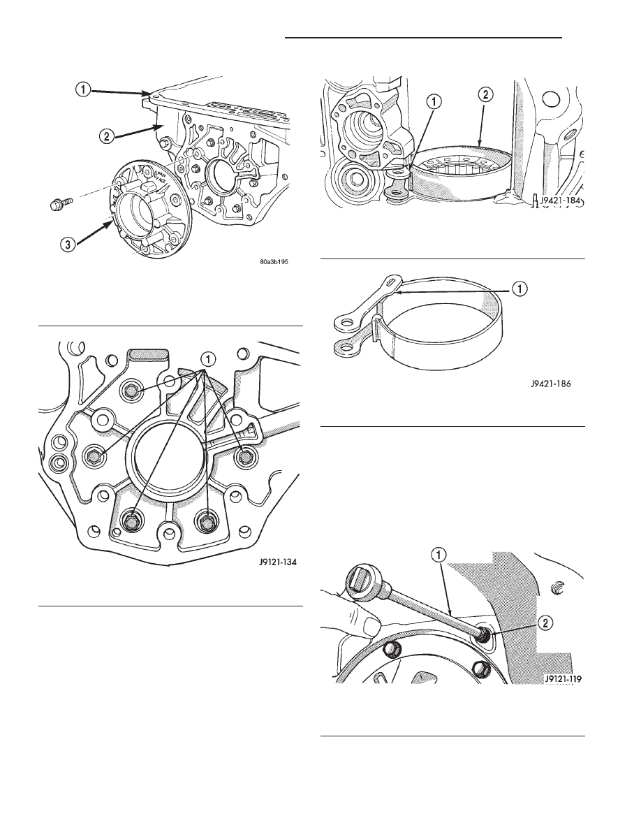
(30) Using snap-ring plier, pull rear band anchor
pin (located on the servo side of the rear support)
from transmission case.
(31) Remove rear band and link from transmission
(Fig. 138).
(32) Separate link from rear band (Fig. 139).
(33) If necessary remove front and rear band servo
levers. All transmission components can be serviced
without removing the levers.
(a) Using a 1/4 inch drive extension remove
front band reaction pin access plug (Fig. 140).
(b) Remove front band reaction pin with pencil
magnet. Pin is accessible from converter housing
side of case (Fig. 141).
(c) Remove front band lever (Fig. 142).
(d) Using snap-ring plier, pull rear band lever
pivot from transmission case (Fig. 143).
(e) Separate rear band servo lever from trans-
mission.
Fig. 136 Rear Support
1 – OIL PAN FACE
2 – TRANSMISSION HOUSING
3 – REAR SUPPORT
Fig. 137 Overrunning Clutch Cam Bolt Locations
1 – OVERRUNNING CLUTCH CAM BOLTS
Fig. 138 Rear Band and Link
1 – LINK
2 – REAR BAND
Fig. 139 Rear Band and Link
1 – NOTCHED SIDE OF LINK GOES TOWARD BAND
Fig. 140 Front Band Reaction Pin Access Plug
1 – 1/4
88
DRIVE EXTENSION
2 – FRONT BAND REACTION PIN ACCESS PLUG
21 - 168
AUTOMATIC TRANSMISSION—30RH
XJ
DISASSEMBLY AND ASSEMBLY (Continued)