Jeep XJ. Manual - part 405


  Index      Jeep     Jeep XJ - service repair manual 2001 year


Search            


Content   ..  403  404  405  406   ..


Jeep XJ. Manual - part 405


Install new seal rings on park gear hub only if orig-
inal rings are damaged, or worn. Install ring with
interlock ends first and ring with plain ends last.
Slip each ring on hub and seat them in grooves. Ver-
ify that rear ring ends are securely interlocked before
proceeding. If the bore in rear support is damaged,
replace the rear support.

(1) Lubricate governor components with Mopar

t

ATF Plus 3, Type 7176 transmission fluid before
assembly.

(2) Clean and inspect governor weights and bores

for scoring or wear. Replace the governor body and
weights if damaged. Refer to Cleaning and Inspection
section of this group for proper procedure.

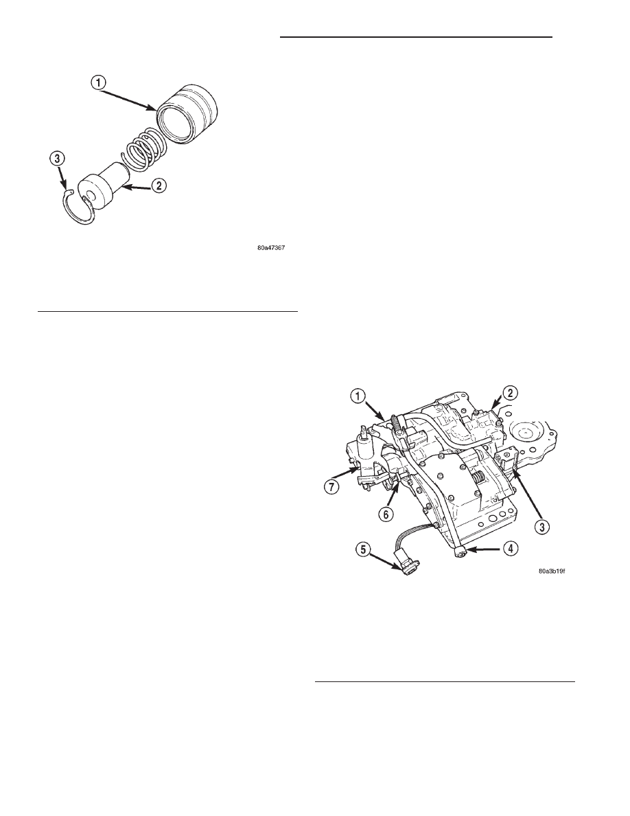
(3) Insert spring into intermediate weight.
(4) Insert inner weight into intermediate weight

and install snap-ring (Fig. 92). Verify snap-ring is
fully seated in groove in intermediate weight (Fig.
91).

(5) Assemble governor weights into governor body

(Fig. 90).

(6) Install washer and snap ring to hold weights in

governor body.

(7) Install governor body in transmission

VALVE BODY

DISASSEMBLY

Position the valve body on a clean work surface to

avoid contamination.

CAUTION: Do not clamp any part of the valve body
assembly (Fig. 93) in a vise. This practice will dis-
tort the valve body and transfer plate resulting in
valve bind. Slide valves and plugs out carefully. Do
not use force at any time. The valves and valve

body will be damaged if force is used. Also tag or
mark the valve body springs for reference as they
are removed. Do not allow them to become inter-
mixed.

(1) Remove

screws

attaching

adjusting

screw

bracket to valve body and transfer plate. Hold
bracket firmly against spring force while removing
last screw.

(2) Remove adjusting screw bracket, line pressure

adjusting screw (Fig. 94).

(3) Remove switch valve and spring, pressure reg-

ulator valve and spring, kickdown valve and spring,
and throttle valve from valve body (Fig. 94).

(4) Secure detent ball and spring in housing with

Retainer Tool 6583 (Fig. 95).

(5) Remove manual shaft E-clip, washer, and seal

(Fig. 96).

(6) Pull manual shaft and park rod assembly

upward out of valve body and off throttle lever (Fig.
96).

(7) Remove manual valve from valve body (Fig. 97)
(8) Remove Retainer Tool 6583. Then remove and

retain detent ball and spring (Fig. 96).

(9) Remove throttle lever (Fig. 96).

(10) Remove park rod E-clip and separate rod from

manual lever (Fig. 98).

Fig. 92 Intermediate and Inner Governor Weights

1 – INTERMEDIATE WEIGHT
2 – INNER WEIGHT
3 – SNAP-RING

Fig. 93 Valve Body Assembly

1 – VALVE BODY
2 – CONVERTER CLUTCH MODULE
3 – SOLENOID
4 – PARK ROD
5 – CONVERTER CLUTCH SOLENOID CONNECTOR
6 – MANUAL VALVE
7 – MANUAL LEVER

21 - 156

AUTOMATIC TRANSMISSION—30RH

XJ

DISASSEMBLY AND ASSEMBLY (Continued)

(11) Remove converter clutch solenoid from separa-

tor plate (Fig. 99). A T25 torx bit is required to
remove solenoid attaching screw.

(12) Remove screws attaching converter clutch

module to valve body and remove module and con-
necting tube (Fig. 100).

(13) Remove screws attaching end cover plate to

torque converter module (Fig. 101).

(14) Remove converter clutch valve, fail safe valve,

and springs (Fig. 101)

(15) Turn valve body over so transfer plate is fac-

ing upward (Fig. 102). With valve body in this posi-
tion, valve body check balls will remain in place and
not fall out when transfer plate is removed.

(16) Remove screws attaching transfer plate to

valve body (Fig. 102).

(17) Remove transfer plate and separator plate

from valve body (Fig. 102). Note position of filter and
clutch solenoid for reference. Remove valve body
check balls.

Fig. 94 Adjusting Screw Bracket, Springs, Valve

Removal

1 – ADJUSTER BRACKET
2 – LINE PRESSURE ADJUSTER
3 – PRESSURE REGULATOR VALVE
4 – SWITCH VALVE
5 – VALVE BODY
6 – TRANSFER PLATE
7 – THROTTLE VALVE
8 – SLEEVE
9 – KICKDOWN VALVE
10 – THROTTLE PRESSURE ADJUSTER

Fig. 95 Securing Detent Ball And Spring With

Retainer Tool

1 – SPECIAL TOOL 6583
2 – DETENT BALL AND SPRING HOUSING

Fig. 96 Manual And Throttle Levers

1 – PARK ROD
2 – E-RING
3 – WASHER
4 – MANUAL LEVER
5 – MANUAL VALVE
6 – SPRING
7 – DETENT BALL
8 – VALVE BODY

Fig. 97 Manual Valve

1 – MANUAL VALVE
2 – VALVE BODY

XJ

AUTOMATIC TRANSMISSION—30RH

21 - 157

DISASSEMBLY AND ASSEMBLY (Continued)

(18) Position transfer plate on bench so separator

plate, and filter are facing up. This will avoid having
rear clutch and rear servo check balls fall out when
plates are separated.

(19) Remove screws attaching separator plate to

transfer plate (Fig. 103).

(20) Note position of filter, rear clutch servo and

rear servo check balls for assembly reference (Fig.
103) and (Fig. 104).

(21) Remove shuttle valve end plate (Fig. 105).
(22) Remove shuttle valve E-clip and remove sec-

ondary spring and spring guides from end of valve
(Fig. 106).

Fig. 100 Clutch Module And Connecting Tube

1 – MODULE AND CONNECTING TUBE

Fig. 98 Park Rod

1 – MANUAL LEVER
2 – E-CLIP
3 – PARK ROD

Fig. 99 Converter Clutch Solenoid

1 – VALVE BODY
2 – TORQUE CONVERTER CLUTCH SOLENOID

Fig. 101 Converter Clutch and Fail Safe Valves

1 – COVER PLATE
2 – CONVERTER CLUTCH VALVE
3 – TORQUE CONVERTER CLUTCH MODULE
4 – MODULE CONNECTING TUBE
5 – FAIL-SAFE VALVE

Fig. 102 Valve Body Transfer Plate Screws

1 – TRANSFER PLATE
2 – VALVE BODY
3 – SEPARATOR PLATE

21 - 158

AUTOMATIC TRANSMISSION—30RH

XJ

DISASSEMBLY AND ASSEMBLY (Continued)

(23) Remove governor plug end plate (Fig. 107).
(24) Remove 1-2 and 2-3 shift valve governor plugs

from valve body (Fig. 107).

(25) Remove shuttle valve throttle plug, primary

spring and shuttle valve from valve body (Fig. 107).

(26) Remove

screws

attaching

kickdown

limit

valve body to valve body (Fig. 107).

(27) Remove 1-2 shift control valve and spring

from valve body (Fig. 107).

(28) Remove 2-3 shift valve and spring from valve

body (Fig. 107).

(29) Remove 1-2 shift valve and spring from valve

body (Fig. 107).

(30) Remove throttle pressure plug from kickdown

limit valve body (Fig. 107).

(31) Remove retainer from end of kickdown limit

valve body (Fig. 107).

(32) Remove kickdown limit valve and spring from

kickdown limit valve body (Fig. 107).

(33) Remove regulator valve end plate from valve

body (Fig. 107).

(34) Remove regulator valve line pressure plug,

pressure plug sleeve, regulator valve throttle pres-
sure plug and spring (Fig. 107).

ASSEMBLY

Clean and inspect all valve body components for

damage or wear. Refer to the Cleaning and Inspec-
tion section of this group for proper procedure.

Fig. 103 Transfer And Separator Plates

1 – SEPARATOR PLATE
2 – FILTER
3 – TRANSFER PLATE

Fig. 104 Rear Servo and Rear Clutch Check Balls

1 – REAR SERVO CHECK BALL
2 – TRANSFER PLATE
3 – REAR CLUTCH CHECK BALL

Fig. 105 Shuttle Valve End Plate

1 – VALVE BODY
2 – SHUTTLE VALVE END PLATE

Fig. 106 Shuttle Valve E-Clip And Secondary Spring

1 – E-CLIP
2 – SECONDARY SPRING AND GUIDES
3 – SHUTTLE VALVE

XJ

AUTOMATIC TRANSMISSION—30RH

21 - 159

DISASSEMBLY AND ASSEMBLY (Continued)


Content   ..  403  404  405  406   ..