Jeep XJ. Manual - part 384


  Index      Jeep     Jeep XJ - service repair manual 2001 year


Search            


Content   ..  382  383  384  385   ..


Jeep XJ. Manual - part 384


(7) Install Adapter 6747-2A on front bearing hub of

countershaft, if not previously done. The adapter has
a shoulder on one side. The shoulder goes toward the
countershaft.

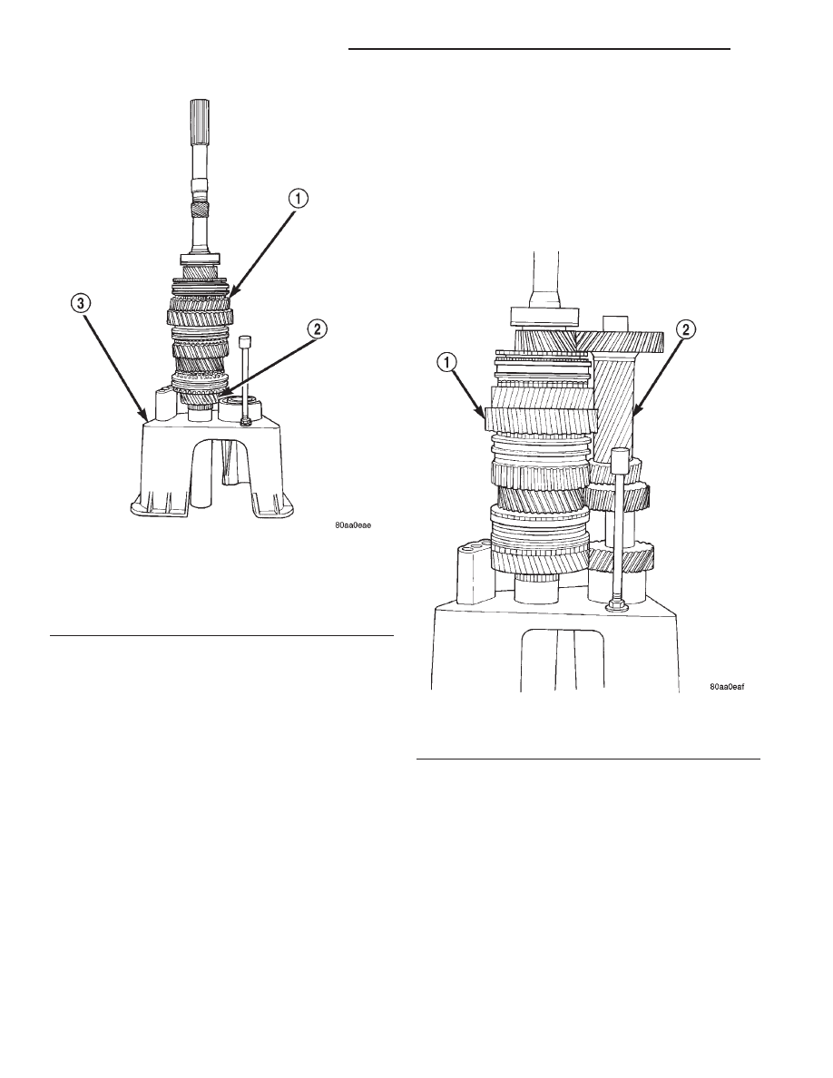
(8) Slide countershaft (and adapter) into fixture

slot. Verify that countershaft and output shaft gears
are fully meshed with the mainshaft gears before
proceeding (Fig. 95).

(9) Check alignment of countershaft and output

shaft gear teeth. Note that gears may not align per-
fectly. A difference in height of 1.57 to 3.18 mm (1/16
to 1/8 in.) will probably exist. This difference will not
interfere with assembly. However, if the difference is
greater than this, the countershaft adapter tool is
probably upside down. Remove countershaft, reverse
adapter tool, reinstall countershaft and check align-
ment again.

Fig. 94 Output Shaft And Geartrain Installed In Input

Shaft

1 – OUTPUT SHAFT AND GEARTRAIN
2 – INPUT SHAFT
3 – SPECIAL TOOL

6747

Fig. 95 Countershaft Installed On Fixture Tool

1 – OUTPUT SHAFT AND GEARTRAIN
2 – COUNTERSHAFT (SLIDE INTO PLACE ON FIXTURE TOOL)

21 - 72

NV3550 MANUAL TRANSMISSION

XJ

DISASSEMBLY AND ASSEMBLY (Continued)

(10) Position reverse idler in support cup of assem-

bly fixture (Fig. 96). Be sure idler gear is properly
meshed and aligned with shaft gear teeth and that
bolt holes are facing out and not toward geartrain.
Adjust pedestal up or down if necessary. Also be sure
that short end of idler shaft is facing up as shown.

(11) On 2-wheel drive transmission, thread one

Pilot Stud 8120 in center or passenger side hole of
output shaft bearing retainer. Then position retainer
on fifth gear as shown (Fig. 97).

(12) Assemble 1-2 and fifth reverse-shift forks (Fig.

98). Arm of fifth-reverse fork goes through slot in 1-2
fork.

Fig. 96 Reverse Idler Assembly Positioned On

Assembly Fixture Pedestal

1 – OUTPUT SHAFT AND GEARTRAIN
2 – COUNTERSHAFT
3 – REVERSE IDLER ASSEMBLY
4 – TOOL PEDESTAL

Fig. 97 Positioning Output Shaft Bearing Retainer

For Rear Housing Installation

1 – SPECIAL TOOL

8120

2 – OUTPUT SHAFT BEARING RETAINER

Fig. 98 Assembling 1-2 And Fifth-Reverse Shift

Forks

1 – INSERT ARM THROUGH 1–2 FORK
2 – 1–2 FORK
3 – FIFTH-REVERSE FORK

XJ

NV3550 MANUAL TRANSMISSION

21 - 73

DISASSEMBLY AND ASSEMBLY (Continued)

(13) Install

assembled

shift

forks

in

synchro

sleeves (Fig. 99). Be sure forks are properly seated in
sleeves.

REAR HOUSING—2WD

(1) Drive adapter housing alignment dowels back

into housing until dowels are flush with mounting
surface (Fig. 100).

(2) Apply liberal quantity of petroleum jelly to

countershaft rear bearing and bearing race.

(3) Install countershaft rear bearing in bearing

race (Fig. 101).

CAUTION: The

countershaft

bearings

can

be

installed backwards if care is not exercised. Be
sure the large diameter side of the roller retainer
faces the countershaft and the small diameter side
faces the race and housing (Fig. 102).

(4) Apply extra petroleum jelly to hold counter-

shaft rear bearing in place when housing is installed.

(5) Apply light coat of petroleum jelly to shift shaft

bushing/bearing in rear housing (Fig. 102).

(6) Reach into countershaft rear bearing with fin-

ger, and push each bearing roller outward against
race. Then apply extra petroleum jelly to hold rollers
in place. This avoids having rollers becoming dis-
placed during housing installation. This will result in
misalignment

between

bearing

and

countershaft

bearing hub.

Fig. 99 Shift Forks Installed In Synchro Sleeves

1 – SYNCHRO SLEEVES
2 – FORK ARMS
3 – SHIFT FORKS

Fig. 100 Preparing Rear Housing Dowels For

Installation

1 – HOUSING ALIGNMENT DOWELS
2 – REAR HOUSING
3 – DOWEL FLUSH WITH SURFACE

Fig. 101 Lubricating Countershaft Rear Bearing

1 – COUNTERSHAFT REAR BEARING
2 – REAR BEARING RACE
3 – REAR HOUSING
4 – PETROLEUM JELLY (APPLY TO BEARING AND RACE)

21 - 74

NV3550 MANUAL TRANSMISSION

XJ

DISASSEMBLY AND ASSEMBLY (Continued)

(7) Install rear housing onto geartrain (Fig. 103).

Be sure bearing retainer pilot stud is in correct bolt
hole in housing. Also be sure countershaft and output
shaft bearings are aligned in housing and on counter-
shaft. It may be necessary to lift upward on counter-
shaft slightly to ensure that the countershaft rear
bearing engages to the countershaft before the rear
output shaft bearing engages the housing.

(8) Seat rear housing on output shaft rear bearing

and countershaft. Use plastic or rawhide mallet to
tap housing into place.

(9) Install the three bolts that secure rear bearing

retainer to rear housing as follows:

(a) Apply Mopar

t Gasket Maker, or equivalent,

to bolt threads, bolt shanks and under bolt heads
(Fig. 104).

(b) Start first two bolts in retainer (Fig. 105). It

may be necessary to move retainer rearward (with
pilot stud) in order to start bolts in retainer.

(c) Remove Pilot Stud 8120 and install last

retainer bolt (Fig. 105).

(d) Tighten all three retainer bolts to 30-35 N·m

(22-26 ft. lbs.) torque.

Fig. 102 Countershaft Rear Bearing Seated In

Seated in Race

1 – SHIFT SHAFT BUSHING/BEARING
2 – COUNTERSHAFT REAR BEARING (SEATED IN RACE)

Fig. 103 Rear Housing Installation—2WD

1 – REAR HOUSING
2 – SHIFT FORKS AND GEARTRAIN

Fig. 104 Applying Sealer To Retainer And Housing

Bolts

1 – MOPAR GASKET MAKER (OR LOCTITE 518)
2 – RETAINER AND HOUSING BOLTS
3 – APPLY SEALER TO UNDERSIDE OF BOLT HEAD, SHANK

AND THREADS

Fig. 105 Removing Pilot Stud Tool And Installing

Retainer Bolts—2WD

1 – BEARING RETAINER BOLT
2 – SPECIAL TOOL 8120

XJ

NV3550 MANUAL TRANSMISSION

21 - 75

DISASSEMBLY AND ASSEMBLY (Continued)


Content   ..  382  383  384  385   ..