Jeep XJ. Manual - part 382


  Index      Jeep     Jeep XJ - service repair manual 2001 year


Search            


Content   ..  380  381  382  383   ..


Jeep XJ. Manual - part 382


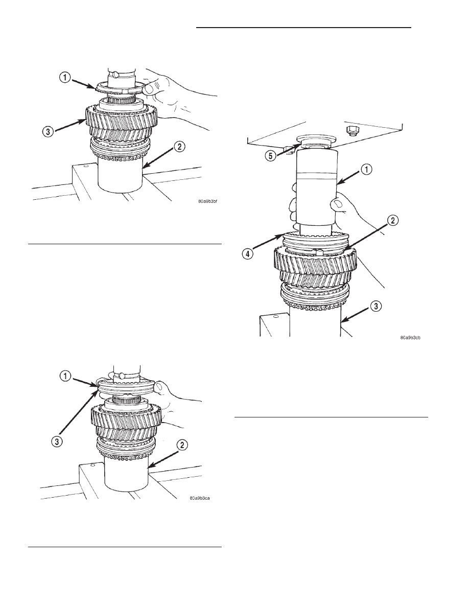
(16) Install first gear synchro ring (Fig. 69).

(17) Assemble 1-2 synchro hub sleeve, springs,

struts and detent balls.

CAUTION: The 1-2 synchro hub and sleeve can be
installed backwards if care is not exercised. One
side of the synchro sleeve is marked First Gear
Side. Be sure this side of the sleeve will face first
gear after installation.

(18) Start 1-2 synchro assembly on shaft by hand

(Fig. 70). Be sure synchro sleeve is properly positioned.
Side marked first side must be facing first gear.

(19) Press 1-2 synchro onto output shaft using

suitable size pipe tool and shop press (Fig. 71).

CAUTION: Take time to align the synchro ring and
sleeve as hub the is being pressed onto the shaft.
The synchro ring can be cracked if it becomes mis-
aligned.

(20) Install interm ring.
(21) Install new 1-2 synchro hub snap ring (Fig.

72) as follows:

(a) Snap rings are available in thicknesses from

1.80 mm to 2.00 mm (0.070 to 0.078 in.).

(b) Install thickest snap ring that will fit in

shaft groove.

(c) Verify that snap ring is completely seated in

groove before proceeding.
(22) Install second gear synchro ring in 1-2 syn-

chro hub and sleeve (Fig. 73). Be sure synchro ring is
properly seated in sleeve.

Fig. 69 First Gear Synchro Ring Installation

1 – FIRST GEAR SYNCHRO RING
2 – SPECIAL TOOL 6310–1
3 – FIRST GEAR

Fig. 70 Starting 1-2 Synchro On Shaft

1 – 1–2 SYNCHRO ASSEMBLY
2 – SPECIAL TOOL 6310–1
3 – BE SURE THIS IS “FIRST GEAR SIDE” OF SYNCHRO

SLEEVE

Fig. 71 Pressing 1-2 Synchro Assembly Onto Output

Shaft

1 – SUITABLE SIZE PIPE TOOL
2 – SYNCHRO RING
3 – SPECIAL TOOL

6310–1

4 – 1–2 SYNCHRO ASSEMBLY
5 – PRESS RAM

21 - 64

NV3550 MANUAL TRANSMISSION

XJ

DISASSEMBLY AND ASSEMBLY (Continued)

(23) Install synchro friction cone and synchro cone

in synchro ring.

(24) Install second gear needle bearing on shaft

(Fig. 74).

(25) Install second gear onto shaft and bearing

(Fig. 75). Make sure that second gear is fully seated
on synchro components.

Fig. 72 Installing 1-2 Synchro Hub Snap Ring

1 – 1–2 SYNCHRO
2 – SPECIAL TOOL

6310–1

3 – SYNCHRO SNAP RING

Fig. 73 Second Gear Synchro Ring Installation

1 – SECOND GEAR SYNCHRO RING
2 – 1–2 SYNCHRO
3 – SPECIAL TOOL

6310–1

Fig. 74 Second Gear Bearing Installation

1 – SECOND GEAR BEARING
2 – SPECIAL TOOL

6310–1

Fig. 75 Second Gear Installation

1 – SPECIAL TOOL

6310–1

2 – 1–2 SYNCHRO ASSEMBLY
3 – BEARING
4 – SECOND GEAR

XJ

NV3550 MANUAL TRANSMISSION

21 - 65

DISASSEMBLY AND ASSEMBLY (Continued)

(26) Install two-piece thrust washer (Fig. 76). Be

sure washer halves are seated in shaft groove and
that washer lugs are seated in shaft lug bores. Also,
ensure that the i.d. grooves and markings noted dur-
ing removal are facing the correct direction.

(27) Start retaining ring around two-piece thrust

washer (Fig. 77). Make sure that the locating dimple
is between the thrust washer halves.

(28) Seat thrust washer retaining ring with plastic

mallet (Fig. 78).

Fig. 76 Installing Two-Piece Thrust Washer

1 – WASHER GROOVE IN SHAFT
2 – LUG BORE
3 – THRUST WASHER LUGS
4 – LUG BORE
5 – LUG
6 – WASHER HALF

Fig. 77 Starting Retaining Ring Over Two-Piece

Thrust Washer

1 – THRUST WASHER RETAINING RING
2 – THRUST WASHER HALVES
3 – SECOND GEAR
4 – LOCATING DIMPLE

Fig. 78 Seating Thrust Washer Retaining Ring

1 – PLASTIC MALLET
2 – THRUST WASHER RETAINING RING

21 - 66

NV3550 MANUAL TRANSMISSION

XJ

DISASSEMBLY AND ASSEMBLY (Continued)

(29) Install third gear needle bearing on shaft (Fig.

79).

(30) Install third gear on shaft and bearing (Fig.

80).

(31) Install third speed synchro ring on third gear

(Fig. 81).

(32) Assemble 3-4 synchro hub, sleeve, springs,

struts and detent balls.

CAUTION: The 3-4 synchro hub and sleeve can be
installed backwards if care is not exercised. One
side of the sleeve has grooves in it. Be sure this
side of sleeve is also facing the front of the shaft.

(33) Start 3-4 synchro hub on output shaft splines

by hand (Fig. 82).

(34) Press 3-4 synchro assembly onto output shaft

with shop press and suitable size pipe tool (Fig. 83).
Make sure that the tool presses on hub as close to
output shaft as possible but does not contact the
shaft splines.

Fig. 79 Third Gear Bearing Installation

1 – THIRD GEAR BEARING

Fig. 80 Installing Third Gear

1 – THIRD GEAR
2 – BEARING

Fig. 81 Third Speed Synchro Ring Installation

1 – THIRD SPEED SYNCHRO RING
2 – THIRD GEAR

Fig. 82 Starting 3-4 Synchro Hub On Output Shaft

1 – GROOVED SIDE OF SLEEVE (TO FRONT)
2 – 3–4 SYNCHRO ASSEMBLY

XJ

NV3550 MANUAL TRANSMISSION

21 - 67

DISASSEMBLY AND ASSEMBLY (Continued)


Content   ..  380  381  382  383   ..