Jeep XJ. Manual - part 381


  Index      Jeep     Jeep XJ - service repair manual 2001 year


Search            


Content   ..  379  380  381  382   ..


Jeep XJ. Manual - part 381


REVERSE IDLER DISASSEMBLY

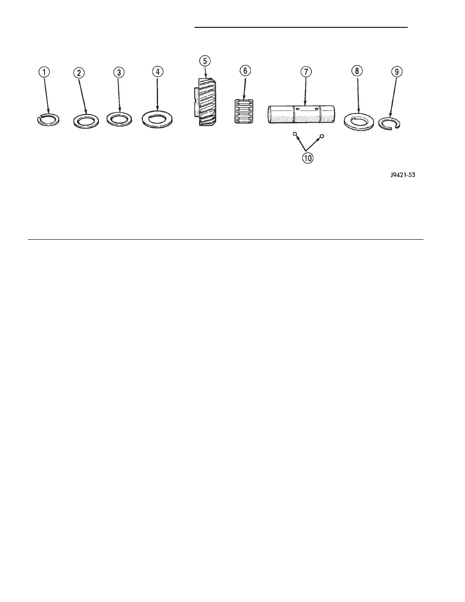
(1) Remove idler gear snap rings (Fig. 57).
(2) Remove thrust washer, wave washer, thrust

plate and idler gear from shaft.

(3) Remove idler gear needle bearing from shaft.

ASSEMBLY

Gaskets are not used in the NV3550 transmission.

Sealers are used at all case joints. Recommended
sealers are Mopar

t Gasket Maker for all case joints

and Mopar

t silicone sealer, or equivalent, for the

input shaft bearing retainer. Apply these products as
indicated in the assembly procedures.

NOTE: It is very important that the transmission
shift components be in Neutral position during
assembly. This is necessary to prevent damaging
synchro and shift components when the housings
are installed.

The 3-4, 1-2 and fifth-reverse synchro hub snap

rings can be fitted selectively. New snap rings are
available in 0.05 mm (0.0019 in.) thickness incre-
ments. Use the thickest snap ring that will fit in
each snap ring groove.

SYNCHRONIZER

The easiest method of assembling each synchro is

to install the springs, struts and detent balls one at a
time as follows:

(1) Slide the sleeve part way onto the hub. Leave

enough room to install the spring in the hub and the
strut in the hub groove.

(2) Install the first spring in the hub. Then install

a strut over the spring. Be sure the spring is seated
in the spring bore in the strut.

(3) Slide the sleeve onto the hub just far enough to

hold the first strut and spring in place.

(4) Place the detent ball in the top of the strut.

Then carefully work the sleeve over the ball to hold
it in place. A small flat blade screwdriver can be used
to press the ball into place while moving the sleeve
over it.

(5) Repeat

the

procedure

for

the

remaining

springs, struts and balls. Tape, or a rubber band can
be used to temporarily secure each strut and ball as
they are installed.

(6) Verify synchro assembly. Be sure the three

springs, struts and detent balls are all in place (Fig.
58).

Fig. 57 Reverse Idler Components

1 – SNAP RING
2 – FLAT WASHER
3 – WAVE WASHER
4 – THRUST WASHER
5 – REVERSE IDLER GEAR

6 – IDLER GEAR BEARING
7 – IDLER SHAFT
8 – THRUST WASHER
9 – SNAP RING
10 – THRUST WASHER LOCK BALLS

21 - 60

NV3550 MANUAL TRANSMISSION

XJ

DISASSEMBLY AND ASSEMBLY (Continued)

OUTPUT SHAFT

(1) Lubricate shaft, gears and bearings with rec-

ommended lubricant during assembly. Petroleum
jelly can be used to hold parts in place.

(2) Check bearing surfaces of output shaft for

nicks or scratches. Smooth surfaces with 320/400 grit
emery cloth if necessary. Apply oil to emery cloth and
shaft surface before polishing.

(3) Inspect and replace any synchro ring that

exhibits wear or damage. Completely immerse each
synchro ring in lubricant before installation.

(4) Lubricate and install reverse gear needle bear-

ing on shaft (Fig. 59). Slide bearing up against shoul-
der on output shaft.

(5) Install reverse gear over needle bearing (Fig.

60).

(6) Install solid brass synchro ring on reverse gear

(Fig. 61).

Fig. 58 Assembled View Of Synchro Components

1 – SLEEVE
2 – HUB SHOULDER
3 – SPRING (3)
4 – STRUT (3)
5 – DETENT BALL (3)
6 – HUB

Fig. 59 Reverse Gear Bearing Installation

1 – REVERSE GEAR BEARING
2 – SHOULDER

Fig. 60 Reverse Gear Installation

1 – REVERSE GEAR

Fig. 61 Reverse Gear Synchro Ring Installation

1 – REVERSE GEAR
2 – SYNCHRO RING (SOLID BRASS)

XJ

NV3550 MANUAL TRANSMISSION

21 - 61

DISASSEMBLY AND ASSEMBLY (Continued)

(7) Assemble fifth-reverse synchro hub, sleeve,

struts, springs and detent balls, if not previously
done.

CAUTION: The

fifth-reverse

synchro

hub

and

sleeve can be installed backwards if care is not
exercised. One side of the hub has shoulders
around the hub bore. Make sure this side of the hub
is facing the front of the shaft. In addition, one side
of the sleeve is tapered. Be sure the sleeve is
installed so the tapered side will be facing the front
of the shaft.

(8) Start fifth-reverse synchro assembly on output

shaft splines by hand. Then seat synchro onto shaft
with shop press and Remover 6310-1 (Fig. 62).

(9) Install new fifth-reverse hub snap ring (Fig.

63) as follows:

(a) Snap rings are available in thicknesses from

2.00 mm to 2.20 mm (0.078 to 0.086 in.).

(b) Install thickest snap ring that will fit in

shaft groove.

(c) Verify that snap ring is completely seated in

groove before proceeding.

(10) Install fifth gear synchro ring in synchro hub

and sleeve (Fig. 64).

(11) Install fifth gear bearing. Spread bearing only

enough to clear shoulder on output shaft (Fig. 65). Be
sure bearing is properly seated after installation.

(12) Install fifth gear on shaft and onto bearing

(Fig. 66).

Fig. 62 Fifth-Reverse Synchro Assembly Installation

1 – SPACER
2 – PRESS RAM
3 – REVERSE GEAR
4 – FIFTH-REVERSE SYNCHRO ASSEMBLY
5 – SPECIAL TOOL

6310–1

6 – PRESS BLOCKS
7 – OUTPUT SHAFT

Fig. 63 Installing Fifth-Reverse Synchro Hub Snap

Ring

1 – FIFTH-REVERSE SYNCHRO ASSEMBLY
2 – SNAP RING
3 – PRESS BED
4 – PRESS BLOCKS

Fig. 64 Installing Fifth Gear Synchro Ring

1 – FIFTH-SPEED SYNCHRO RING
2 – FIFTH-REVERSE SYNCHRO ASSEMBLY

21 - 62

NV3550 MANUAL TRANSMISSION

XJ

DISASSEMBLY AND ASSEMBLY (Continued)

(13) Invert output shaft and set the shaft in

Remover 6310-1 so that fifth gear is seated on the
tool (Fig. 67).

(14) Install first gear bearing on output shaft (Fig.

67). Be sure bearing is seated on shaft shoulder and
is properly joined.

(15) Install first gear on shaft and over bearing

(Fig. 68). Make sure bearing synchro cone is facing
up as shown.

Fig. 65 Installing Fifth Gear Bearing

1 – SHAFT SHOULDER
2 – FIFTH GEAR BEARING

Fig. 66 Fifth Gear Installation

1 – FIFTH GEAR
2 – BEARING

Fig. 67 First Gear Bearing Installation

1 – FIRST GEAR BEARING
2 – SHAFT SHOULDER
3 – SPECIAL TOOL

6310–1

4 – PRESS BLOCKS

Fig. 68 First Gear Installation

1 – FIRST GEAR
2 – SPECIAL TOOL

6310–1

3 – BEARING

XJ

NV3550 MANUAL TRANSMISSION

21 - 63

DISASSEMBLY AND ASSEMBLY (Continued)


Content   ..  379  380  381  382   ..