Jeep XJ. Manual - part 373


  Index      Jeep     Jeep XJ - service repair manual 2001 year


Search            


Content   ..  371  372  373  374   ..


Jeep XJ. Manual - part 373


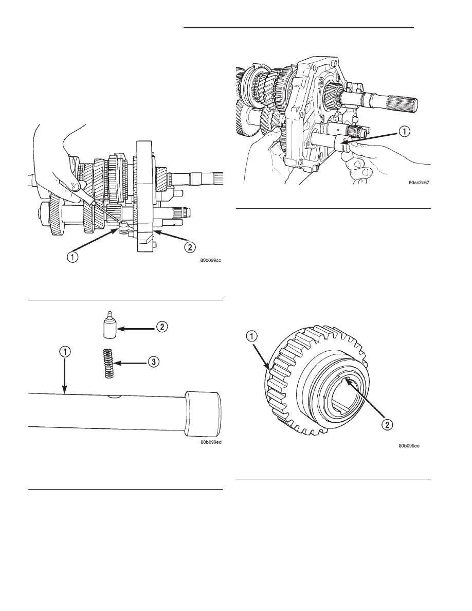
(32) Install the compression spring and pin into

the reverse idler gear shaft (Fig. 88).

(33) Install the reverse idler shaft through the

intermediate plate and reverse idler gear assembly
(Fig. 89) until the idler shaft pin contacts the gear
assembly. Make sure that the notched cut-out in the
idler shaft is to the rear of the transmission.

(34) Align the pin with the alignment notch in the

reverse idler gear assembly (Fig. 90). The alignment
notch in the reverse idler gear race/hub is a small
relief cut above one of the main longitudinal slots. Be
sure that the pin is aligned with the proper slot, the
opposite slot has an oil drain hole which the pin will
drop into. The assembly will then be locked onto the
shaft and will need to be disassembled in order to be
removed.

(35) Depress

compression

spring

and

pin

in

reverse idler gear shaft (Fig. 91).

(36) Install

the

reverse

idler

gear

shaft

the

remainder of the way through the reverse idler gear
assembly.

Fig. 87 Reverse Shift Arm Position

1 – REVERSE SHIFT ARM
2 – INTERMEDIATE PLATE

Fig. 88 Install Compression Spring And Pin

1 – REVERSE IDLER GEAR SHAFT
2 – PIN
3 – COMPRESSION SPRING

Fig. 89 Install Reverse Idler Shaft

1 – REVERSE IDLER SHAFT

Fig. 90 Align Idler Shaft Pin

1 – REVERSE IDLER GEAR ASSEMBLY
2 – ALIGNMENT NOTCH

21 - 28

AX5 MANUAL TRANSMISSION

XJ

DISASSEMBLY AND ASSEMBLY (Continued)

(37) Position the reverse idler gear shaft lock plate

onto the intermediate plate.

(38) Install a new bolt to hold the idler gear shaft

lock plate to the intermediate plate.

(39) Install the fifth gear thrust ring lock ball to

the countershaft (Fig. 92).

(40) Install the fifth gear thrust ring onto the

countershaft and over the lock ball (Fig. 93).

(41) Install fifth gear shift fork to the countershaft

fifth gear assembly.

(42) Install the countershaft fifth gear bearings

into the countershaft fifth gear assembly.

(43) Position the countershaft fifth gear assembly

on the countershaft. Ensure that the fifth gear fork is
installed onto the fifth gear shift rail.

(44) Install the fifth gear synchro ring.
(45) Position the fifth gear blocker ring onto the

countershaft.

(46) Using a suitable mallet and spacer, tap the

fifth gear blocker ring onto the countershaft.

(47) Install new bolt to hold fifth gear shift fork to

the fifth gear shift rail (Fig. 94).

(48) Measure countershaft fifth gear thrust clear-

ance.

(49) Select a snap-ring so that the thrust clearance

is 0.10–0.30 mm (0.004–0.010 in.).

(50) Install snap-ring to hold fifth gear blocker

ring onto countershaft.

Fig. 91 Depress Pin In Reverse Idler Gear Shaft

1 – DEPRESS PIN

Fig. 92 Install Fifth Gear Thrust Ring Lock Ball

1 – PENCIL MAGNET
2 – CLUSTER GEAR
3 – LOCK BALL RECESS
4 – THRUST RING LOCK BALL

Fig. 93 Install Fifth Gear Thrust Ring

1 – LOCK BALL NOTCH
2 – FIFTH GEAR THRUST RING

Fig. 94 Install Fifth Gear Retainer Bolt

1 – SHIFT FORK RETAINER BOLT
2 – FIFTH GEAR SHIFT RAIL
3 – FIFTH GEAR SHIFT FORK

XJ

AX5 MANUAL TRANSMISSION

21 - 29

DISASSEMBLY AND ASSEMBLY (Continued)

(51) Remove intermediate plate from vise and

remove bolts and washers from intermediate.

COUNTERSHAFT

DISASSEMBLY

(1) Remove select fit snap-ring holding the coun-

tershaft front bearing onto the countershaft (Fig. 95).

(2) Using Bearing Splitter P-334, a suitable spacer

on center of countershaft, and a shop press, remove
the countershaft front bearing from the countershaft.

ASSEMBLY

(1) Remove any nicks or burrs on countershaft hub

with fine emery or crocus cloth.

(2) Position countershaft front bearing on end of

countershaft.

(3) Using Special Tool 8109 and a shop press,

press bearing onto countershaft.

(4) Select the thickest snap-ring that will fit into

the snap-ring groove of the countershaft (Fig. 95).

(5) Install snap-ring to hold countershaft front

bearing onto countershaft.

INPUT SHAFT

DISASSEMBLY

(1) Verify that the 3–4 synchronizer is in the neu-

tral position.

(2) Separate input shaft from output shaft (Fig.

96). Note that the output shaft pilot bearing is an
uncaged roller type bearing.

(3) Remove the output shaft pilot bearing rollers

from the input shaft and the output shaft.

(4) Remove the fourth gear synchronizer ring from

the input shaft (Fig. 97).

(5) Remove the select fit snap-ring holding the

input shaft bearing onto the input shaft.

(6) Using Bearing Splitter P-334 and a shop press,

remove the bearing from the input shaft.

ASSEMBLY

(1) Position input shaft bearing onto input shaft.
(2) Using Driver L-4507, drive bearing onto input

shaft.

(3) Select the thickest snap-ring that will fit into

the snap-ring groove of the input shaft (Fig. 98).

(4) Lubricate output shaft pilot bearing bore of

input shaft with petroleum jelly.

I. D.

MARK

SNAP RING THICKNESS MM (IN.)

1
2
3
4
5
6

2.05 - 2.10
2.10 - 2.15
2.15 - 2.20
2.20 - 2.25
2.25 - 2.30
2.30 - 2.35

(0.0807 - 0.0827)
(0.0827 - 0.0846)
(0.0846 - 0.0866)
(0.0866 - 0.0886)
(0.0886 - 0.0906)
(0.0906 - 0.0925)

Fig. 95 Countershaft Front Bearing Snap-ring

Fig. 96 Separate Input and Output Shafts

1 – INPUT SHAFT ASSEMBLY
2 – OUTPUT SHAFT AND GEAR ASSEMBLY

Fig. 97 Input Shaft Components

1 – BEARING
2 – SYNCHRO RING
3 – INPUT SHAFT
4 – BEARING SNAP RING

21 - 30

AX5 MANUAL TRANSMISSION

XJ

DISASSEMBLY AND ASSEMBLY (Continued)

(5) Install output shaft pilot bearing rollers in

input shaft bore (Fig. 99). Ensure to use sufficient
petroleum jelly to hold rollers in position.

(6) Install the fourth gear synchronizer ring onto

the input shaft.

(7) Install input shaft to output shaft. Use care

when mating the two shafts not to displace any out-
put shaft pilot bearing rollers.

OUTPUT SHAFT

DISASSEMBLY

(1) Remove input shaft and output shaft pilot

bearing rollers from output shaft.

(2) Measure and note thrust clearance of output

shaft gears (Fig. 100). Clearance should be 0.10 –
0.25 mm (0.004 – 0.010 in.).

I. D. Mark

Snap Ring Thickness mm (in.)

0
1
2
3
4
5

2.05-2.10 (0.0807-0.0827)
2.10-2.15 (0.0827-0.0846)
2.15-2.20 (0.0846-0.0866)
2.20-2.25 (0.0866-0.0886)
2.25-2.30 (0.0886-0.0906)
2.30-2.35 (0.0906-0.0925)

Fig. 98 Select Input Shaft Bearing Snap-ring

Fig. 99 Install Output Shaft Pilot Bearing Rollers

1 – INPUT SHAFT
2 – BEARING ROLLERS

Fig. 100 Check Output Shaft Gear Thrust Clearance

XJ

AX5 MANUAL TRANSMISSION

21 - 31

DISASSEMBLY AND ASSEMBLY (Continued)


Content   ..  371  372  373  374   ..