Jeep XJ. Manual - part 361


  Index      Jeep     Jeep XJ - service repair manual 2001 year


Search            


Content   ..  359  360  361  362   ..


Jeep XJ. Manual - part 361


(4) Install O-rings and teflon rings over the

O-rings on valve body.

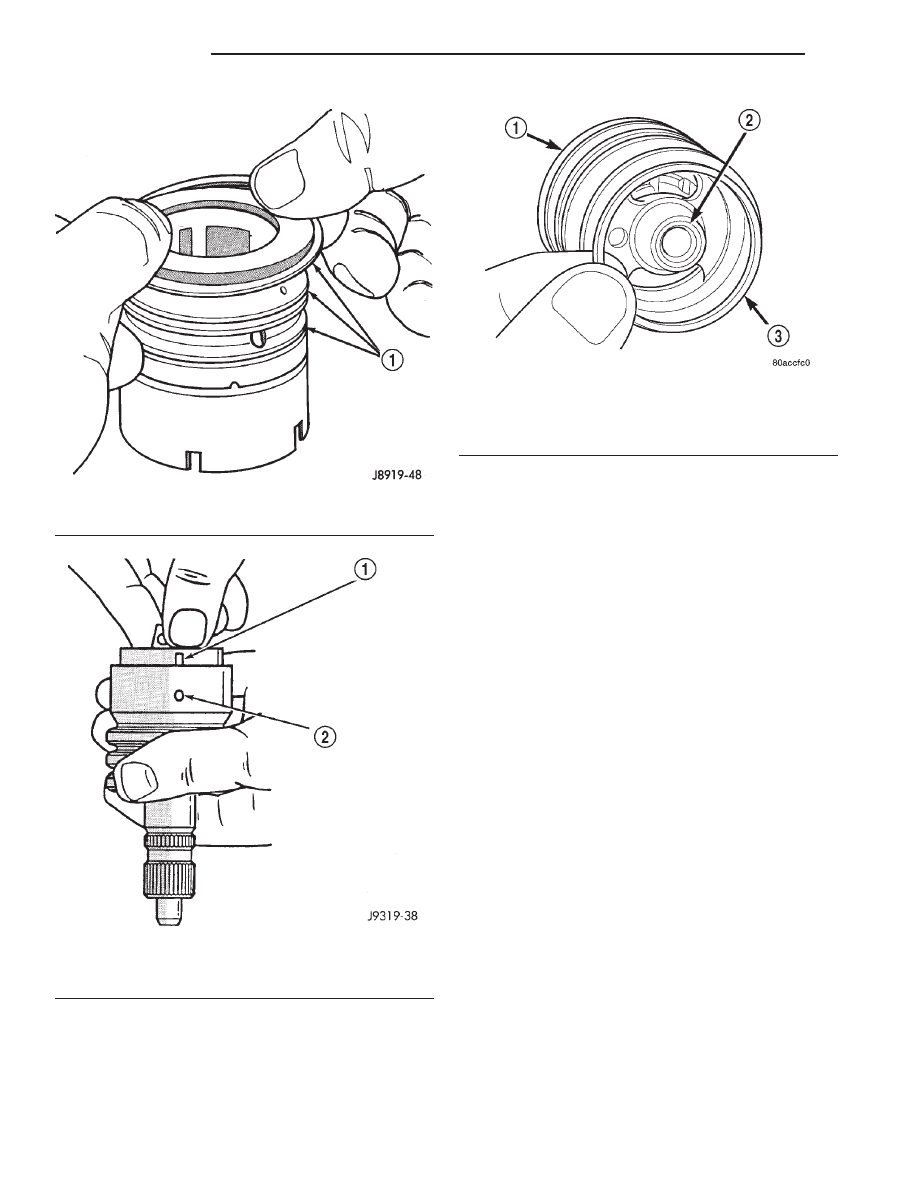
(5) Install O-ring into the back of the stub shaft

cap (Fig. 15).

(6) Install stub shaft and valve assembly in the

housing. Line up worm shaft to slots in the valve
assembly.

(7) Install thrust support assembly.

NOTE: The thrust support is serviced as an assem-
bly. If any component of the thrust support is dam-
aged the assembly must be replaced.

(8) Install adjuster nut and lock nut.
(9) Adjust Thrust Bearing Preload and Over-Cen-

ter Rotating Torque.

RACK PISTON AND WORM SHAFT

DISASSEMBLY

(1) Remove housing end plug.
(2) Remove rack piston plug (Fig. 16).
(3) Remove side cover and pitman shaft.
(4) Turn stub shaft COUNTERCLOCKWISE until

the rack piston begins to come out of the housing.

(5) Insert Arbor C-4175 into bore of rack piston

(Fig. 17) and hold tool tightly against worm shaft.

(6) Turn the stub shaft with a 12 point socket

COUNTERCLOCKWISE, this will force the rack pis-
ton onto the tool and hold the rack piston balls in
place.

(7) Remove the rack piston and tool together from

housing.

(8) Remove tool from rack piston.
(9) Remove rack piston balls.
(10) Remove clamp bolts, clamp and ball guide

(Fig. 18).

(11) Remove teflon ring and O-ring from the rack

piston (Fig. 19).

Fig. 13 Valve Seals

1 – O-RING SEALS

Fig. 14 Stub Shaft Installation

1 – NOTCH IN CAP
2 – VALVE BODY PIN

Fig. 15 Stub Shaft Cap O-Ring

1 – VALVE BODY
2 – STUB SHAFT CAP
3 – O-RING

19 - 16

STEERING

XJ

DISASSEMBLY AND ASSEMBLY (Continued)

(12) Remove the adjuster lock nut and adjuster

nut from the stub shaft.

(13) Pull the stub shaft with the spool valve and

thrust support assembly out of the housing.

(14) Remove the worm shaft from the housing

(Fig. 20).

ASSEMBLY

NOTE: Clean and dry all components and lubricate
with power steering fluid.

(1) Check for scores, nicks or burrs on the rack

piston finished surface. Slight wear is normal on the
worm gear surfaces.

Fig. 16 Rack Piston End Plug

1 – EXTENSION
2 – END PLUG
3 – RACK PISTON
4 – RATCHET

Fig. 17 Rack Piston with Arbor

1 – RACK PISTON
2 – SPECIAL TOOL C-4175

Fig. 18 Rack Piston

1 – CLAMP
2 – BALLS
3 – RACK PISTON
4 – BALL GUIDE

Fig. 19 Rack Piston Teflon Ring and O-Ring

1 – TEFLON SEAL
2 – BACK-UP O-RING MUST BE INSTALLED UNDER PISTON

RING

3 – RACK PISTON NUT

XJ

STEERING

19 - 17

DISASSEMBLY AND ASSEMBLY (Continued)

(2) Install O-ring and teflon ring on the rack pis-

ton.

(3) Install worm shaft in the rack piston and align

worm shaft spiral groove with rack piston ball guide
hole (Fig. 21).

CAUTION: The rack piston balls must be installed
alternately into the rack piston and ball guide. This
maintains worm shaft preload. There are 12 black
balls and 12 silver (Chrome) balls. The black balls
are smaller than the silver balls.

(4) Lubricate and install rack piston balls through

return guide hole while turning worm shaft COUN-
TERCLOCKWISE (Fig. 21).

(5) Install remaining balls in guide using grease to

hold the balls in place (Fig. 22).

(6) Install the guide onto rack piston and install

clamp and clamp bolts. Tighten bolts to 4.8 N·m (43
in. lbs.).

(7) Insert Arbor C-4175 into bore of rack piston

and hold tool tightly against worm shaft.

(8) Turn the worm shaft COUNTERCLOCKWISE

while pushing on the arbor. This will force the rack
piston onto the arbor and hold the rack piston balls
in place.

(9) Install the races and thrust bearing on the

worm shaft and install shaft in the housing (Fig. 20).

(10) Install the stub shaft with spool valve, thrust

support assembly and adjuster nut in the housing.

(11) Install the rack piston and arbor tool into the

housing.

(12) Hold arbor tightly against worm shaft and

turn stub shaft CLOCKWISE until rack piston is
seated on worm shaft.

(13) Install pitman shaft and side cover in the

housing.

(14) Install rack piston plug and tighten to 150

N·m (111 ft. lbs.).

(15) Install housing end plug.
(16) Adjust worm shaft thrust bearing preload and

over-center rotating torque.

Fig. 20 Worm Shaft

1 – GEAR HOUSING
2 – BEARING RACE
3 – WORM SHAFT
4 – BEARING

Fig. 21 Installing Balls in Rack Piston

1 – INSTALL BALLS IN THIS HOLE WHILE SLOWLY ROTATING

WORM COUNTER CLOCKWISE

2 – WORM FLANGE

Fig. 22 Balls in the Return Guide

1 – GUIDE
2 – PETROLEUM JELLY
3 – BALLS

19 - 18

STEERING

XJ

DISASSEMBLY AND ASSEMBLY (Continued)

ADJUSTMENTS

STEERING GEAR

CAUTION: Steering gear must be adjusted in the
proper order. If adjustments are not performed in
order, gear damage and improper steering response
may result.

NOTE: Adjusting the steering gear in the vehicle is
not recommended. Remove gear from the vehicle
and drain the fluid. Then mount gear in a vise to
perform adjustments.

WORM THRUST BEARING PRELOAD

(1) Mount the gear carefully into a vise.

CAUTION: Do not overtighten the vise on the gear
case. This may affect the adjustment

(2) Remove adjuster plug locknut (Fig. 23).
(3) Rotate the stub shaft back and forth with a 12

point socket to drain the remaining fluid.

(4) Turn the adjuster in with Spanner Wrench

C-4381. Tighten the plug and thrust bearing in the
housing until firmly bottomed in the housing about
34 N·m (25 ft. lbs.).

(5) Place an index mark on the housing even with

one of the holes in adjuster plug (Fig. 24).

(6) Measure back (counterclockwise) 5.08 mm (0.20

in) and mark housing (Fig. 25).

(7) Rotate adjustment cap back (counterclockwise)

with spanner wrench until hole is aligned with the
second mark (Fig. 26).

(8) Install and tighten locknut to 108 N·m (80 ft.

lbs.). Be sure adjustment cap does not turn while
tightening the locknut.

Fig. 23 Adjuster Lock Nut

1 – ADJUSTER NUT
2 – STEERING GEAR
3 – LOCK NUT
4 – PUNCH

Fig. 24 Alignment Marking On Housing

1 – INDEX

Fig. 25 Second Marking On Housing

1 – REFERENCE MARK

XJ

STEERING

19 - 19


Content   ..  359  360  361  362   ..