Jeep XJ. Manual - part 318


  Index      Jeep     Jeep XJ - service repair manual 2001 year


Search            


Content   ..  316  317  318  319   ..


Jeep XJ. Manual - part 318


(38) Disconnect the electrical connectors and the

vent hose and from the transfer case and transmis-
sion.

(39) Support the rear of the transmission with a

jack.

(40) Remove the transmission support crossmem-

ber.

(41) Lower the transmission to gain access to the

transmission to engine retaining bolts.

(42) Remove all the bolts securing the transmis-

sion to the engine assembly. Remove the transmis-
sion and the transfer case assembly from the vehicle.

(43) Lower the vehicle from the hoist.
(44) Remove the fan shroud and both cooling fans

as an assembly.

(45) Remove the oil filter and adaptor from the

vehicle as an assembly.

(46) Remove the power steering fluid pressure line

from the steering gear.

(47) Disconnect the electrical connectors from the

bottom of the fuel / water separator.

(48) Drain the fuel / water separator. Refer to

Group 9, Fuel System for the procedure.

(49) Remove the fuel lines from the fuel / water

separator and cap.

(50) Remove the fuel / water separator and mount-

ing bracket assembly from the bulkhead.

(51) Remove all the remaining wiring from the

engine assembly and position it out of the way.

(52) Attach a lifting device to the engine lifting

brackets and slightly raise the weight off the engine
mounts.

(53) Remove the right and left engine mount

throughbolts.

(54) Carefully lift the engine out of the engine

compartment.

INSTALLATION

(1) Carefully place the engine assembly into the

engine compartment..

(2) Install the engine mount throughbolts and nuts

in there original position. Leaving them loose at this
time.

(3) Install the fuel / water separator and mounting

bracket on the bulkhead.

(4) Install the fuel lines on the fuel / water sepa-

rator.

(5) Connect the electrical connectors to the bottom

of the fuel/water separator.

(6) Install the power steering fluid pressure line

on the steering gear.

(7) Install the oil filter and adaptor on the engine.

Torque adaptor retaining bolt to 69 N·m (51 ft. lbs.).
Fill the oil filter prior to installation.

(8) Install the fan shroud and both cooling fans as

an assembly in the vehicle.

(9) Raise the vehicle on a hoist.
(10) Install the transmission and transfer case

assembly in the vehicle.

(11) Install the bolts securing the transmission to

the engine assembly. Torque to 74.6 N·m (55 ft. lbs.).

(12) Position, connect and secure all electrical con-

nectors and vent hoses on the transfer case and
transmission in there original positions.

(13) Install the transmission support crossmember.

Torque bolts to 50 N·m (37 ft. lbs.).

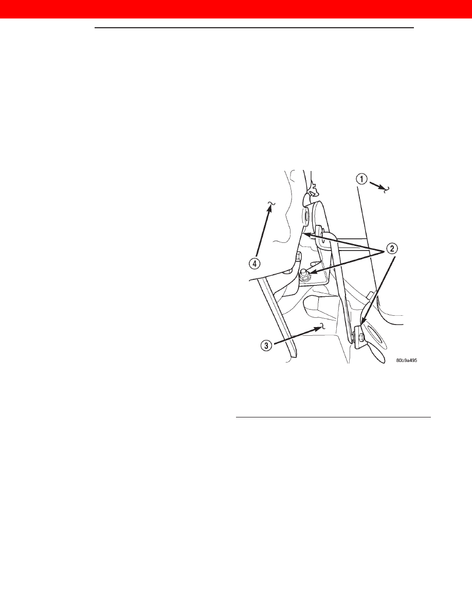
(14) Install the (3) nuts retaining the transfer case

shift linkage (Fig. 20).

(15) Install the clutch slave cylinder on the clutch

housing, making sure the cylinder pushrod is prop-
erly aligned with the clutch fork (Fig. 21).

(16) Connect the exhaust system at the (3) bolt

flange (Fig. 22).

(17) Install the exhaust system support clamp

(Fig. 22).

(18) Install the rear driveshaft in its original posi-

tion.

(19) Install the front driveshaft in its original posi-

tion.

(20) Install the lower fan shroud panel and retain-

ing bolt.

(21) Install the engine ground wire (Fig. 23).
(22) Lower the vehicle from the hoist.

Fig. 20 Transfer Case Shift Linkage — 4x4

1 – FRONT DRIVESHAFT
2 – SHIFTER LINKAGE RETAINING NUTS
3 – TRANSFER CASE
4 – TRANSMISSION

9 - 20

ENGINE

XJ

REMOVAL AND INSTALLATION (Continued)

2000 JEEP CHEROKEE

(23) Working inside the vehicle, install the shifter

on the transmission

(24) Install the shifter boot seal.
(25) Install the center console. Refer to Group 23,

Body for the procedure.

(26) Position, connect and secure all engine wiring

in its original position

(27) On L. H. D. vehicles, connect the heater core

coolant supply and brake vacuum supply hoses on
the engine.

(28) On R. H. D. vehicles, position the steel line

assembly and connect the heater core coolant supply
and the brake vacuum supply hoses on the engine.

(29) Install the coolant reservoir supply hose on

the engine (Fig. 24).

(30) Install the innercooler inlet and outlet hoses

on the engine (Fig. 24).

(31) Install the upper and lower radiator hoses on

the engine.

(32) Fill the cooling system. Refer to Group 7,

Cooling System, for the procedure.

(33) Connect the oil pressure sensor electrical con-

nector (Fig. 24).

(34) Connect the EGR vacuum supply hose on the

engine (Fig. 24).

(35) Install the air filter outlet hose and connect

the breather hose on the engine (Fig. 24).

(36) Install the refrigerant suction and discharge

lines. Torque the retaining bolts on the A/C compres-
sor to 22 N·m (200 in. lbs.). Make sure the O-Rings
are well lubricated and free of tears.

(37) Charge the refrigerant system. Refer to Group

24, Heating and Air Conditioning for the procedure.

(38) Install the manual cooling fan.

Fig. 21 Clutch Slave Cylinder

1 – CLUTCH SLAVE CYLINDER
2 – CLUTCH SLAVE CYLINDER RETAINING NUTS
3 – FRONT DRIVESHAFT

Fig. 22 Exhaust System Inlet Pipe Connection

1 – OIL PAN
2 – EXHAUST INLET PIPE FLANGE RETAINING BOLTS
3 – EXHAUST SYSTEM SUPPORT CLAMP

Fig. 23 Engine Ground Wire Location

1 – RIGHT ENGINE MOUNT THROUGHBOLT NUT
2 – ENGINE GROUND WIRE
3 – OIL PAN

XJ

ENGINE

9 - 21

REMOVAL AND INSTALLATION (Continued)

2000 JEEP CHEROKEE

(39) Connect the electric cooling fan electrical con-

nector.

(40) Install the battery tray.
(41) With assistance from another person, install

the hood.

NOTE: Use the previously marked hinge locations
for alignment reference.

(42) Install the hood retaining bolts.
(43) Install the rivets on the hood latch cable con-

trol assembly.

(44) Install the hood latch assemblies on the hood.
(45) Install and connect the engine compartment

lamp.

(46) Install the battery and connect both of the

battery cables.

(47) Fill the power steering fluid. Refer to Group

19, Steering — Power Steering Pump-Initial opera-
tion for the procedure.

(48) Fill the transmission fluid. Refer to Group 21,

Transmission and Transfer Case for the procedure.

(49) Check the engine oil level before engine start

up.

CYLINDER HEAD COVER

REMOVAL

(1) Disconnect the negative battery cable.

WARNING: DO

NOT

REMOVE

THE

CYLINDER

BLOCK DRAIN PLUGS OR LOOSEN THE RADIATOR
DRAIN COCK WITH THE SYSTEM HOT AND PRES-
SURIZED BECAUSE SERIOUS BURNS FROM THE
COOLANT CAN OCCUR.

(2) On right hand drive vehicles, drain the cooling

system. Refer to Group 7, Cooling System for the pro-
cedure.

(3) Recover

the

air

conditioning

system,

if

equipped. Refer to Group 24, Heating and Air Condi-
tioning for the procedure.

(4) Remove the A/C lines at the compressor and

cap all openings. Refer to Group 24, Heating and Air
Conditioning for the procedure. Remove the A/C line
support bracket attached to cylinder head cover, and
move the A/C, vacuum lines away from the cylinder
head.

(5) Remove the generator support brace.
(6) Remove the Crankcase breather hose from the

rear of the valve cover

(7) Remove the cylinder head cover bolts.
(8) Remove the cylinder head cover.

INSTALLATION

(1) Install the cylinder head cover. Torque the bolts

to 15 N·m (133 in. lbs.).

(2) Connect the crankcase breather hose.
(3) Install the generator support brace. Torque bolt

to 27 N·m (20 ft. lbs.) and nut to 11 N·m (8 ft. lbs.).

(4) Install the A/C lines on the compressor and

install the support bracket on the cylinder head
cover. Torque bolt to 7 N·m (62 in. lbs.).

(5) Connect the negative battery cable.
(6) If equipped with A/C, evacuate and charge the

air conditioning system. Refer to Group 24, Heater
and Air Conditioning.

(7) On right hand drive vehicles, fill the cooling

system. Check for leaks.

WARNING: USE EXTREME CAUTION WHEN THE
ENGINE IS OPERATING. DO NOT STAND IN DIRECT
LINE WITH THE FAN. DO NOT PUT HANDS NEAR
THE PULLEYS, BELTS OR FAN. DO NOT WEAR
LOOSE CLOTHING.

(8) Operate the engine with the radiator cap off.

Inspect for leaks and continue operating the engine
until the thermostat opens. Add coolant, if required.

Fig. 24 LHD Engine Compartment — Diesel

1 – HEATER CORE COOLANT SUPPLY HOSES
2 – INNERCOOLER OUTLET HOSE
3 – AIR FLITER OUTLET HOSE
4 – EGR VACUUM SUPPLY HOSE
5 – OIL PRESSURE SENSOR CONNECTOR
6 – INNERCOOLER INLET HOSE
7 – COOLANT SUPPLY HOSE

9 - 22

ENGINE

XJ

REMOVAL AND INSTALLATION (Continued)

2000 JEEP CHEROKEE

HYDRAULIC TAPPETS

Before disassembling any part of the engine to cor-

rect tappet noise, check the oil pressure. If vehicle
has no oil pressure gauge, install a reliable gauge at
the pressure sending unit. The pressure should be
between 4 bars (50 psi) at 3000 RPM.

Check the oil level after the engine reaches normal

operating temperature. Allow 5 minutes to stabilize
oil level, check dipstick. The oil level in the pan
should never be above the FULL mark or below the
ADD OIL mark on dipstick. Either of these 2 condi-
tions could be responsible for noisy tappets:

OIL LEVEL HIGH
If oil level is above the FULL mark, it is possible

for the connecting rods to dip into the oil. With the
engine running, this condition could create foam in
the oil pan. Foam in oil pan would be fed to the
hydraulic tappets by the oil pump causing them to
lose length and allow valves to seat noisily.

OIL LEVEL LOW
Low oil level may allow oil pump to take in air.

When air is fed to the tappets, they lose length which
allows valves to seat noisily. Any leaks on intake side
of oil pump through which air can be drawn will cre-
ate the same tappet action. Check the lubrication
system from the intake strainer to the pump cover,
including the relief valve retainer cap. When tappet
noise is due to aeration, it may be intermittent or
constant, and usually more than 1 tappet will be
noisy. When oil level and leaks have been corrected,
operate the engine at fast idle. Run engine for a suf-
ficient time to allow all of the air inside the tappets
to be bled out.

HYDRAULIC TAPPETS

REMOVAL

(1) Disconnect the negative battery cable.
(2) Discharge

the

air

conditioning

system,

if

equipped. Refer to Group 24, Heating and Air Condi-
tioning for procedure.

(3) If equipped with air conditioning, remove the

A/C lines at the compressor and cap.

(4) Remove the A/C line bracket attached to the

cylinder head cover and move the lines away from
the cylinder head.

(5) Remove cylinder head cover. Refer to cylinder

head cover removal and installation procedure in this
section.

(6) Remove the rocker assemblies and push rods.

Refer to rocker arms and push rod removal and
installation procedure in this section. Identify push
rods to ensure installation in original location.

(7) Remove cylinder head, intake manifold, and

exhaust manifold. Refer to cylinder head removal
and installation in this section.

(8) Remove the tappet retainers (Fig. 26).

(9) Slide Hydraulic Tappet Remover/Installer Tool

through opening in block and seat tool firmly in the
head of tappet.

(10) Pull the tappet out of the bore with a twisting

motion. If all tappets are to be removed, identify tap-
pets to ensure installation in original location.

CAUTION: The plunger and tappet bodies are not
interchangeable.

The

plunger

and

valve

must

always be fitted to the original body. It is advisable
to work on one tappet at a time to avoid mixing of
parts. Mixed parts are not compatible. DO NOT dis-
assemble a tappet on a dirty work bench.

Fig. 25 Tappet And Rocker Arm Assembly

Fig. 26 Tappet And Retainer

XJ

ENGINE

9 - 23

REMOVAL AND INSTALLATION (Continued)

2000 JEEP CHEROKEE


Content   ..  316  317  318  319   ..