Jeep XJ. Manual - part 156


  Index      Jeep     Jeep XJ - service repair manual 2001 year


Search            


Content   ..  154  155  156  157   ..


Jeep XJ. Manual - part 156


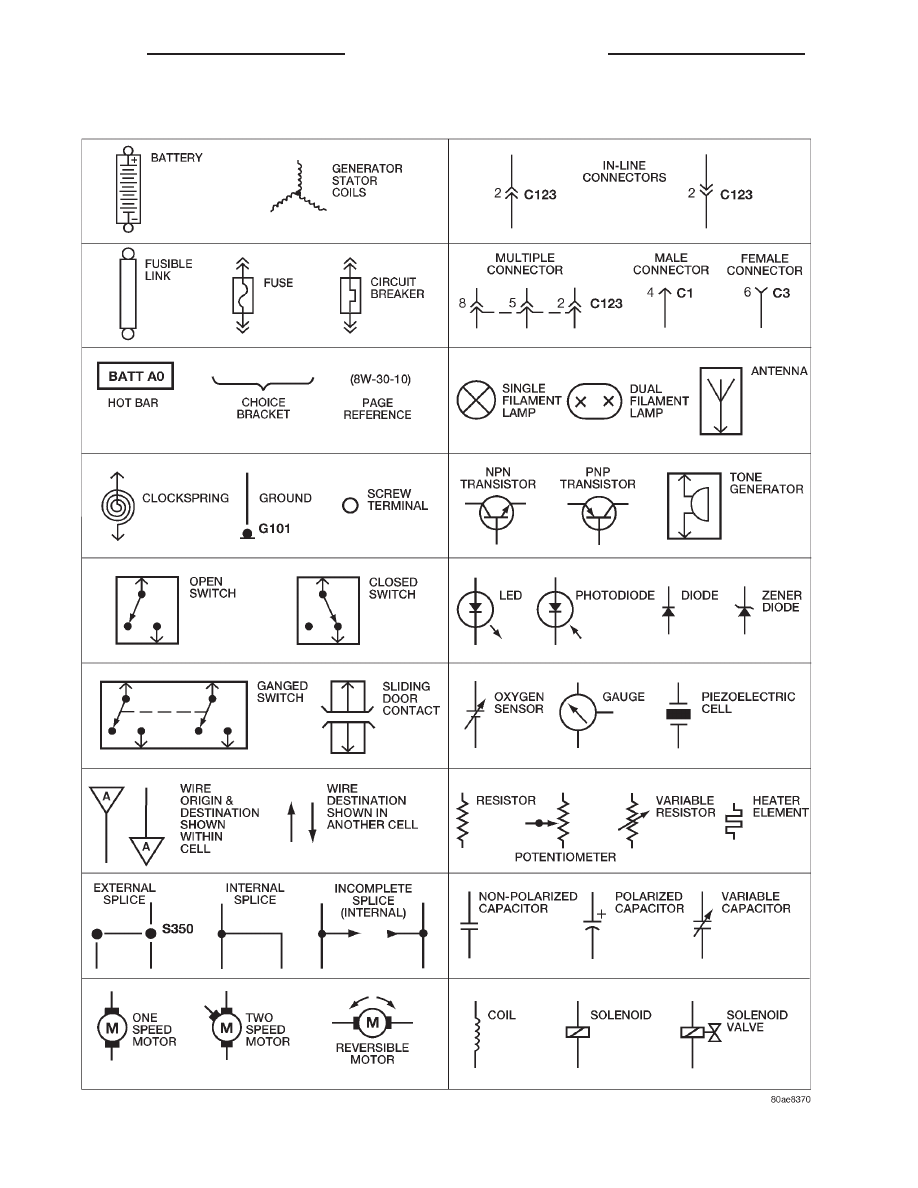
Wiring Diagram Symbols

8W - 01 - 6

8W - 01 GENERAL INFORMATION

XJ

DESCRIPTION AND OPERATION (Continued)

TERMINOLOGY

This a list of terms with there definitions used in

the wiring diagrams.

Built-Up-Export . . . . . . . Vehicles Built For Sale In

Markets Other Than North America

Except-Built-Up-Export . Vehicles Built For Sale In

North America

LHD . . . . . . . . . . . . . . . . Left Hand Drive Vehicles
RHD . . . . . . . . . . . . . . . Right Hand Drive Vehicles
EATX . . . Electronic Automatic Transmission-Front

Wheel Drive

ATX . . Automatic Transmission-Front Wheel Drive
MTX . . . . Manual Transmission-Front Wheel Drive
A/T . . . . Automatic Transmission-Rear Wheel Drive
M/T . . . . . Manual Transmission-Rear Wheel Drive
SOHC . . . . . . . . . . . Single Over Head Cam Engine
DOHC . . . . . . . . . . . . Dual Over Head Cam Engine

CONNECTOR INFORMATION

CAUTION: Not all connectors are serviced. Some
connectors are serviced only with a harness. A typ-
ical example might be the Supplemental Restraint
System connectors. Always check parts availability
before attempting a repair.

IDENTIFICATION

In-line connectors are identified by a number, as

follows:

• In-line connectors located on the engine com-

partment harness are C100 series numbers.

• Connectors located on the instrument panel

harness are C200 series numbers.

• Connectors located on the body harness are

C300 series numbers.

• Jumper harness connectors are C400 series

numbers.

• Grounds and ground connectors are identi-

fied with a “G” and follow the same series number-
ing as the in-line connector.

Component connectors are identified by the compo-

nent name instead of a number. Multiple connectors
on a component use a C1, C2, etc. identifier.

LOCATIONS

Section 8W-90 contains connector/ground location

illustrations. The illustrations contain the connector
name (or number)/ground number and component
identification. Connector/ground location charts in
Section 8W-90 reference the illustration number for
components and connectors.

Section 8W-80 shows each connector and the cir-

cuits involved with that connector. The connectors

are identified using the name/number on the Dia-
gram pages.

SPLICE LOCATIONS

Splice Location charts in Section 8W-70 show the

entire splice, and provide references to other sections
the splice serves.

Section 8W-95 contains illustrations that show the

general location of the splices in each harness. The
illustrations show the splice by number, and provide
a written location.

NOTES, CAUTIONS, and WARNINGS

Throughout this group additional important infor-

mation is presented in three ways; Notes, Cautions,
and Warnings.

NOTES are used to help describe how switches or

components operate to complete a particular circuit.
They are also used to indicate different conditions
that may appear on the vehicle. For example, an
up-to and after condition.

CAUTIONS are used to indicate information that

could prevent making an error that may damage the
vehicle.

WARNINGS provide information to prevent per-

sonal injury and vehicle damage. Below is a list of
general warnings that should be followed any time a
vehicle is being serviced.

WARNING: ALWAYS WEAR SAFETY GLASSES FOR
EYE PROTECTION.

WARNING: USE SAFETY STANDS ANYTIME A PRO-
CEDURE REQUIRES BEING UNDER A VEHICLE.

WARNING: BE SURE THAT THE IGNITION SWITCH
ALWAYS IS IN THE OFF POSITION, UNLESS THE
PROCEDURE REQUIRES IT TO BE ON.

WARNING: SET

THE

PARKING

BRAKE

WHEN

WORKING

ON

ANY

VEHICLE.

AN

AUTOMATIC

TRANSMISSION SHOULD BE IN PARK. A MANUAL
TRANSMISSION SHOULD BE IN NEUTRAL.

WARNING: OPERATE THE ENGINE ONLY IN A
WELL-VENTILATED AREA.

WARNING: KEEP AWAY FROM MOVING PARTS
WHEN THE ENGINE IS RUNNING, ESPECIALLY THE
FAN AND BELTS.

XJ

8W - 01 GENERAL INFORMATION

8W - 01 - 7

DESCRIPTION AND OPERATION (Continued)

WARNING: TO PREVENT SERIOUS BURNS, AVOID
CONTACT WITH HOT PARTS SUCH AS THE RADIA-
TOR, EXHAUST MANIFOLD(S), TAIL PIPE, CATA-
LYTIC CONVERTER, AND MUFFLER.

WARNING: DO NOT ALLOW FLAME OR SPARKS
NEAR

THE

BATTERY.

GASES

ARE

ALWAYS

PRESENT IN AND AROUND THE BATTERY.

WARNING: ALWAYS REMOVE RINGS, WATCHES,
LOOSE HANGING JEWELRY, AND LOOSE CLOTH-
ING.

TAKE OUTS

The abbreviation T/O is used in the component

location section to indicate a point in which the wir-
ing harness branches out to a component.

ELECTROSTATIC DISCHARGE (ESD) SENSITIVE
DEVICES

All ESD sensitive components are solid state and a

symbol (Fig. 2) is used to indicate this. When han-
dling any component with this symbol comply with
the following procedures to reduce the possibility of
electrostatic charge build up on the body and inad-
vertent discharge into the component. If it is not
known whether the part is ESD sensitive, assume
that it is.

(1) Always touch a known good ground before han-

dling the part. This should be repeated while han-
dling the part and more frequently after sliding
across a seat, sitting down from a standing position,
or walking a distance.

(2) Avoid touching electrical terminals of the part,

unless instructed to do so by a written procedure.

(3) When using a voltmeter, be sure to connect the

ground lead first.

(4) Do not remove the part from its protective

packing until it is time to install the part.

(5) Before removing the part from its package,

ground the package to a known good ground on the
vehicle.

DIAGNOSIS AND TESTING

TROUBLESHOOTING TOOLS

When diagnosing a problem in an electrical circuit

there are several common tools necessary. These tools
are listed and explained below.

• Jumper Wire - This is a test wire used to con-

nect two points of a circuit. It can be used to bypass
an open in a circuit.

WARNING: NEVER USE A JUMPER WIRE ACROSS
A

LOAD,

SUCH

AS

A

MOTOR,

CONNECTED

BETWEEN A BATTERY FEED AND GROUND.

• Voltmeter - Used to check for voltage on a cir-

cuit. Always connect the black lead to a known good
ground and the red lead to the positive side of the
circuit.

CAUTION: Most of the electrical components used
in today’s vehicle are solid state. When checking
voltages in these circuits use a meter with a 10-me-
gohm or greater impedance rating.

• Ohmmeter - Used to check the resistance

between two points of a circuit. Low or no resistance
in a circuit means good continuity.

CAUTION: - Most of the electrical components used
in today’s vehicle are Solid State. When checking
resistance in these circuits use a meter with a
10-megohm or greater impedance rating. In addi-
tion, make sure the power is disconnected from the
circuit. Circuits that are powered up by the vehicle
electrical system can cause damage to the equip-
ment and provide false readings.

• Probing Tools - These tools are used for probing

terminals in connectors (Fig. 3). Select the proper
size tool from Special Tool Package 6807, and insert
it into the terminal being tested. Use the other end
of the tool to insert the meter probe.

Fig. 2 Electrostatic Discharge Symbol

Fig. 3 Probing Tool

1 – SPECIAL TOOL 6801
2 – PROBING END

8W - 01 - 8

8W - 01 GENERAL INFORMATION

XJ

DESCRIPTION AND OPERATION (Continued)

INTERMITTENT AND POOR CONNECTIONS

Most intermittent electrical problems are caused

by faulty electrical connections or wiring. It is also
possible for a sticking component or relay to cause a
problem. Before condemning a component or wiring
assembly check the following items.

• Connectors are fully seated

• Spread terminals, or terminal push out

• Terminals in the wiring assembly are fully

seated into the connector/component and locked in
position

• Dirt or corrosion on the terminals. Any amount

of corrosion or dirt could cause an intermittent prob-
lem

• Damaged connector/component casing exposing

the item to dirt and moisture

• Wire insulation that has rubbed through causing

a short to ground

• Some or all of the wiring strands broken inside

of the insulation covering.

• Wiring broken inside of the insulation

TROUBLESHOOTING TESTS

Before beginning any tests on a vehicles electrical

system use the Wiring Diagrams and study the cir-
cuit. Also refer to the Troubleshooting Wiring Prob-
lems in this section.

TESTING FOR VOLTAGE POTENTIAL

(1) Connect the ground lead of a voltmeter to a

known good ground (Fig. 4).

(2) Connect the other lead of the voltmeter to the

selected test point. The vehicle ignition may need to
be turned ON to check voltage. Refer to the appropri-
ate test procedure.

TESTING FOR CONTINUITY

(1) Remove the fuse for the circuit being checked

or, disconnect the battery.

(2) Connect one lead of the ohmmeter to one side

of the circuit being tested (Fig. 5).

(3) Connect the other lead to the other end of the

circuit being tested. Low or no resistance means good
continuity.

TESTING FOR A SHORT TO GROUND

(1) Remove the fuse and disconnect all items

involved with the fuse.

(2) Connect a test light or a voltmeter across the

terminals of the fuse.

(3) Starting at the fuse block, wiggle the wiring

harness about six to eight inches apart and watch
the voltmeter/test lamp.

(4) If the voltmeter registers voltage or the test

lamp glows, there is a short to ground in that gen-
eral area of the wiring harness.

TESTING FOR A SHORT TO GROUND ON FUSES
POWERING SEVERAL LOADS

(1) Refer to the wiring diagrams and disconnect or

isolate all items on the suspected fused circuits.

(2) Replace the blown fuse.
(3) Supply power to the fuse by turning ON the

ignition switch or re-connecting the battery.

Fig. 4 Testing for Voltage Potential

Fig. 5 Testing for Continuity

1 – FUSE REMOVED FROM CIRCUIT

XJ

8W - 01 GENERAL INFORMATION

8W - 01 - 9

DIAGNOSIS AND TESTING (Continued)


Content   ..  154  155  156  157   ..